

Technical Information
(and more)
Triumph
Spitfire Performance Enhancements (August
2014 edition)
Why
bother improving Spitfire performance?
Triumph Spitfires are basically fun, economical street-legal go-carts. Many are still around (more than 300,000 were manufactured from 1962 to 1980), they are simple and easy to work on, and parts are relatively inexpensive and readily available. The later model Spitfire is not a bad-handling car in factory spec. It bested its contemporaries in handling and it holds its own even now. However, some simple changes and upgrades, especially to the early Spitfires, can significantly improve handling and enhance safety. Power, acceleration and speed are where the Spitfire was mediocre in its day, and by today's standards it's underwhelming. But here again, a few simple, relatively inexpensive and easy changes can yield significant improvement, and by putting it all together you will have a much more fun car. The following article is a brief summary and represents my own observations and findings for putting together a fun, reliable and safe Spitfire that can be used with confidence on the street for years and years.
This article is aimed at improving Spitfire performance for sporty
street use at reasonable cost. It’s not a race car
preparation
guide,
although the physics is universal and many of the specific enhancements
apply to both street and track use.
There are several good race preparation guides for Spitfires written by
people with experience building and racing Spitfires. These include the
Triumph Race Prep Manuals, Kas Kastner's race prep guidelines and Jon
Wolfe's "A Guide To Racing Your Triumph Spitfire or GT6." Furthermore,
I’ve limited the scope of enhancements herein to things that
keep a
Spitfire a Spitfire—or at least a Triumph for the most
part—and do not
go into things like radical
engine swaps or drivetrain transformations
(notwithstanding how fascinating, fun and exciting they can be). This
article is meant to benefit Spitfire enthusiasts who want to reliably
use their Spitfires often, improve their performance and derive more
enjoyment from them without having to go to extremes. I attempt
throughout to explain "why"—the
principles
behind the improvements—followed by "what"—the
specific improvements
themselves—to promote understanding and foster creativity.
More
in-depth information can be found in references cited
throughout the article. Exact details of “how” to
implement the
improvements are more the realm of shop manuals and so "how-to"
information is not covered in great detail here. This article is
divided into two main sections—Handling and
Power—and in each section,
the enhancements are listed serially in rough logical order. However,
like any engineered assembly, the Spitfire is a system. Changes involve
trade-offs and often these changes need
to be considered in the context of the
whole vehicle and executed in concert. I hope you
find
this information helpful.
HANDLING
Suspension Basics
Weight
Alignment
Wheels and Tires
Wheel Studs
Front Suspension
Rear Suspension
Anti-Roll Bars
Dampers
Bushings
Brakes
POWER
Torque and Power
Gearing
Weight
Ignition
Exhaust
Intake
Cylinder Head
Compression
Camshaft
Machining Tolerances
Bottom End
"Spit-6"
Fuel Injection
Forced Induction
Other
Understand Some Suspension Basics
The
main purpose of the suspension is to ensure proper positioning of the
tires relative to the road for good grip, despite bumps, dips and
cornering forces, to enable safer and faster handling. The entire
suspension--tires, wheels, linkage, springs and dampers (shock
absorbers)--and the overall rigidity and mass properties of the
vehicle are a system that should be considered as a whole when making
changes to any of the individual elements. The mass of the vehicle and
how it is distributed, the geometry of the suspension elements and the
stiffness of the springs and the damping coefficients of the damping
elements determine how much and how quickly the vehicle will roll,
pitch and yaw in reaction to gravity and handling forces.

At any given point in time with any given set of forces, weight is
being transferred through the suspension to the ground, and the key
principle behind suspension tuning is that the load path with the most
stiffness will transfer the most weight. If more force is
transferred
through a given tire than it can handle, exceeding it's ability to
adhere to the road, then it will lose grip and slide, and control will
be relinquished. If the front of the vehicle slides first, it's called
understeer (or pushing, or plowing), and if the rear of the vehicle
slides first, it's called oversteer (or getting loose or fishtailing).
The objective of performance suspension tuning is to manage weight
transfer, enabling higher cornering and acceleration/braking forces
while staying within the limits of tire adhesion. This is done
primarily by managing mass, the height of the center of mass (a.k.a.
center of gravity, or c.g.), and the length of the moment arms that
forces on the c.g. react through to reach the ground by managing the
geometry of the suspension linkage, and by setting the compliance of
the suspension by managing the geometry of the suspension linkage and
the stiffness of springs and dampers. Generally, the following are good
things for handling: less mass, more concentrated mass (i.e., lower
polar moment of inertia), lower c.g., shorter distances between mass
centers and roll centers (i.e., shorter moment arms—good for
reducing lateral weight transfer due to body roll of sprung mass),
lower roll centers, wider track, and longer wheelbase. These may sound
simple but their implementations sometimes work against each other and
other objectives of vehicle design, and entail various costs and
disadvantages, so suspension solutions are many and varied.
What
ultimately matters here are the forces where the rubber literally meets
the road, i.e., the forces of the accelerating mass of the car versus
the reaction forces of the ground. Wheel rates, which are the product
of spring rates and the leverage and motion of the suspension, are the
actual rates of vehicle stiffness. Simply adding wheel rate
contributions from individual suspension elements yields total wheel
rates and vehicle stiffness. Spring rates alone mean nothing as a
measure of vehicle stiffness and they can be very misleading--it is
wheel rates that matter. I've
tabulated various factory and aftermarket front coil, front anti-roll
bar (ARB) and rear leaf spring
rates
and resultant wheel rates and roll stiffnesses for
nominal Spitfires and GT6s.
Lose
Weight, i.e., "Add Lightness"
All
else being the same, a lighter car will out-handle a heavy one.
Trimming weight is easy to do on the later U.S. market Spitfires by
removing all the extra bumper and bumper reinforcing hardware they were
burdened with. This light weighting will not only make the car less
massive, it will eliminate weight at the ends of the vehicle, thus
reducing its polar moment of inertia, meaning it will be easier to
start and
stop it turning. Moreover, many people think this conversion to the
European spec look or pre-1974 U.S spec look improves the car's
appearance. Best of all, it's free. There are other ways to
“add
lightness” such as replacing various bits and pieces with
lighter ones.
Weight reduction boosts performance, and every little bit counts.
Before discussing the following changes to the front and rear suspension, it is important to review alignment. There are six spatial degrees of freedom: translation along and rotation about each of three spatial axes. The three most basic alignment measures are Caster, Camber and Toe, and they are critical to handling, tire wear and safety. Changes to the suspension will result in changes in alignment that need to be measured and adjusted.


On the Spitfire, caster, camber and toe can be adjusted at the front
reasonably easily. The Spitfire front suspension is a
classic unequal A-arm design. Caster and camber can be adjusted
using shims between the lower A-arms and the frame rails. Addition of
shims adds negative camber. Adding or subtracting unequal numbers of
shims between the front
and rear A-arm interfaces changes caster (more shims at the aft
mounting
adds positive caster). Adjusting the tie rods sets toe.
Note that because of the tie rod geometry, Spitfires exhibit a
significant amount of toe change with up and down (bump and droop)
suspension motion, called bump steer. Therefore, when changing camber
and caster, toe must be checked and reset, and toe should be adjusted
last.

At the rear of the Spitfire is a swing axle architecture with a single
transverse leaf spring. The swing axles themselves are the
primary suspension links; the transverse
leaf spring and trailing radius arms guide the swing axles up and down
and
locate them fore and aft.
Rear caster is for all practical purposes not adjustable, camber
is determined by rear ride height (an intrinsic feature of the swing
axle design), but toe is adjustable using shims where the radius arms
interface with the vehicle
tub. After achieving final ride height and hence rear camber, toe
should be measured and then adjusted if necessary (rear toe changes
much less than front toe).

Stock alignment specs vary across models and can be found in
shop manuals. Specific non-stock settings are mentioned during the
subsequent discussion of suspension mods. Overview information on
generic
alignment metrology and the effects of alignment can be found
in the
following primer:
A Short Course on Wheel Alignment
Install
Better Tires and Wheels

The
use of even
wider
wheels and tires is
possible, but selection of the proper wheel offset is critical for
avoiding interference
between the
tires and the car's bodywork or suspension elements.
Moreover, offset combined with the steering axis, rim width, camber and
overall wheel/tire
diameter determines scrub
radius, which is the distance between the steering axis and
the
centerline of the tire at the ground (on the Spitfire, the steering
axis is the line that goes through the center of the vertical link ball
joint and trunnion; stock Spitfires have positive scrub radius).
Minimizing scrub radius will distribute loads better
on
the wheel bearings, help enable good tracking and
straight-line braking (i.e., help minimize pull to one side or the
other), make steering easy and help minimize tire wear.

There are wheel and tire fitment procedures you can follow to check and see by direct measurement what wheel and tire combinations ought to fit your car. When there is rubbing on a Spitfire, it typically occurs at the inner edges of the front fender lips during up and down suspension motion and at the firewall just aft of the front tires during turns. Too much width and/or not enough offset is usually the root of the problem. Other rub areas can be at the rear radius arms and rear fenders. Generally, using tires wider than 185mm and bigger than 22 inches in overall diameter requires rolling or folding-up of the inner edges of the front fenders, especially if the vehicle has been lowered. Of course, if you do body work to flare the fenders, you can build-to-suit and avoid rubbing the fenders this way and expand the range of wheels and tires even more.
Note that ever-larger wheels and lower profile tires are not
necessarily better. Bigger diameter rims and tires are typically
heavier, so they add unsprung weight. Moreover, their mass is
distributed at a larger radius from the hub so they have more
rotational inertia and so they are more difficult to start and stop
rotating. Lower aspect ratio tires are less compliant, so they may not
be matched to the rest of the suspension. Given the large amount of
rear camber change that Spitfires exhibit, a moderate profile tire with
some compliance is best for grip. Besides, very low aspect tires leave
the wheels more susceptible to damage from objects and potholes in the
road. Lastly, be sure that the wheels won't interfere with the front
brake calipers. Virtually all 13 inch wheel options will work with
stock Spitfire Girling 12 calipers (mk1 and mk2) and Girling 14
calipers (mk3, mkIV and 1500), but TR7 wheels interfere with the larger
Girling 16 calipers for the GT6 due to their offset (see brake upgrades
later in this article).
Install Thicker, Longer Wheel Studs
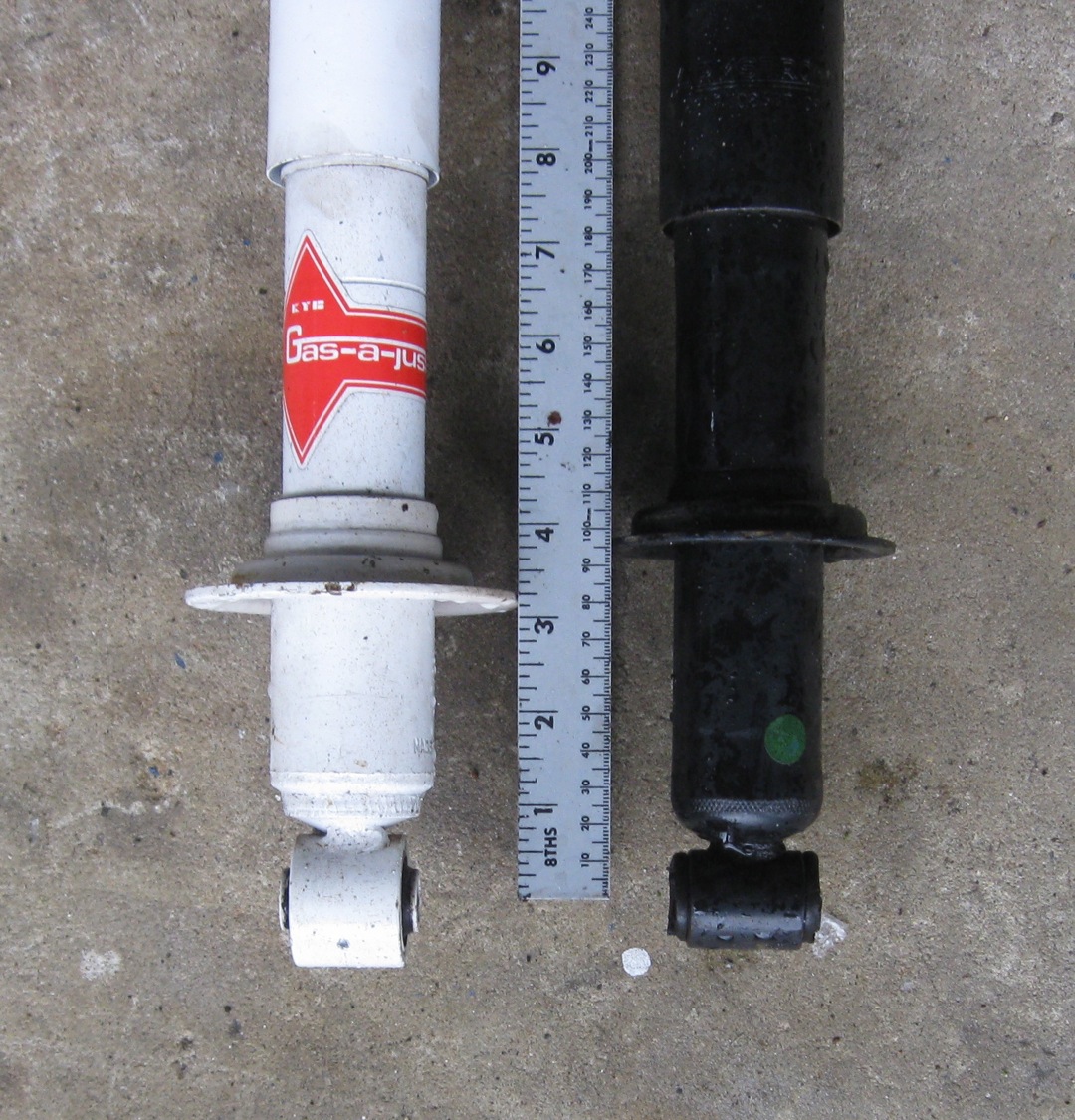
Something to seriously consider, especially when using alloy rims, is to upgrade from the stock 3/8 inch, 24 threads per inch wheel studs to ones that are thicker, longer and stronger. Being as thin as the stock studs are, they are susceptible to over-torquing, and being as old as many are, they likely have been over torqued by someone in the past. Fitting wider wheels with wider, stickier tires allows the car to generate more cornering force, which puts more stress on the studs. Furthermore, alloy rims have thicker center sections than steel ones, and so the lug nuts engage fewer threads, making a somewhat marginal situation even more so. Upgrading to 7/16 inch or 12mm studs that are longer than the stock Spitfire/GT6 ones is good insurance, and a really good idea if you are considering driving your Spitfire sportingly. One very good solution is to upgrade to Land Rover Freelander studs (part number CLP9037L). These are 12mm thick, 1.5mm per thread (i.e., M12x1.5) and are 2 inches long, 1 1/4 inches of which is threaded, versus the stock studs that are 1.5 inches long, 3/4 inches of which is threaded. The comparison photo below clearly illustrates the dramatic difference.

For more details, see Upgrading
Triumph Spitfire Wheel Studs.
Changing wheel alignment and lowering and stiffening the Spitfire can improve handling. Lowering brings the c.g. and roll centers closer to the ground, which helps reduce jacking and roll in turns, which helps maintain proper suspension geometry during turns, which keeps the tires in proper contact with the road so they can grip, which enables faster speeds through turns. Similarly, some suspension geometry changes and stiffening can reduce pitch (i.e., dive during braking and squat during acceleration) and limit bump steer. Stiffening helps by limiting the amount of roll and suspension geometry change for a given amount of acceleration. Moreover, stiffer springs reduce the amount of travel for a given load to offset the loss of bump travel due to lowering.

Some
lowering and stiffening is good, but too much makes things worse. Too
much lowering generates poor suspension geometry that lowers the roll
center too much, thereby lengthening the lever arm between the roll
center and the c.g. to increase the roll moment that increases lateral
weight transfer due to body roll and increases changes in suspension
geometry to actually make
handling worse (note however that simply reducing overall wheel/tire
diameter beneficially lowers the c.g. and roll centers without changing
the linkage geometry). Moreover, too much lowering leaves inadequate
ground
clearance for everyday use. Too much stiffness actually reduces grip
and makes for an uncomfortable ride. Too much change in stiffness at
one end of the car relative to the other, or stiffness not matched to
the static weight distribution of the car, will lead to excessive
understeer or oversteer. The right amount of lowering and stiffening
can optimize the geometry of the suspension links so that the car
transfers less weight for a given amount of roll, as well as rolls less
in response to a given set of forces to help maintain better tire
geometry for good grip.

A good compromise static front suspension geometry for a stiffened Spitfire at rest on level ground is when the lower A-arms are parallel to the ground. This is a reasonable compromise that lowers both the c.g. and the roll center without increasing the roll moment too much. This geometry occurs when the total distance between the center of the bolt attaching the damper to the lower A-arm and the upper spring seat is 10.25 inches. Because the distance from the lower A-arm to damper (shock absorber) connection and the bottom spring seat is nominally 3.25 inches, this also corresponds to a compressed length of the front coil springs installed of 7 inches.

Ways to lower the front include 1) shortening the stock springs, 2) replacing the stock springs with shorter ones and 3) installing front dampers (shock absorbers) that have adjustable height spring seats. Dampers with adjustable spring seats allow fine adjustment of static ride height and provide the most flexibility, but fixed seat dampers will yield the desired ride height if used with springs that have the right combination of stiffness and free length. Stiffer springs reduce the amount of travel for a given load, thereby helping to offset the loss of bump travel due to lowering. The least expensive way to lower the front is to simply cut one free coil off one end of each of the stock springs. This shortens and slightly stiffens the springs, and the pigtail left by this operation will compress and not be an issue once installed in the car. On the Spitfire 1500, this will result in the desired installed static coil length of about 7 inches. Another option is to cut about half a free coil off one end of each spring and then heat and carefully reform and flatten the cut ends. However, this is not easy to do correctly. The application of too much heat can ruin the temper of the springs, and getting two springs to come out the same is difficult and not guaranteed. In either case, this shortening of the stock springs will stiffen them only marginally (about 10 percent). While additional stiffness is good because it limits suspension travel and helps offset the loss of bump travel that comes with lowering, such a marginal increase is not enough. Another approach for the Spitfire 1500 is to install springs from a Spitfire mk3 or mkIV. These springs are shorter in free length but also softer than stock 1500 ones, and using them on a 1500 will lower the front end and result in an installed spring length of about 7¼ inches. Softening while lowering is bad though because the need for suspension travel is increased at the same time the amount of bump travel is reduced, thus greatly increasing the likelihood of bottoming-out the suspension. Therefore, using softer springs like those from an earlier model Spitfire on a 1500 is not recommended. Running out of suspension travel and hitting the bump stops is harsh, leads to sudden understeer and can cause loss of control and is potentially damaging. Replacement springs need to be stiff enough to be compatible with the reduction in bump travel but not so stiff as to make handling worse, so the right approach is to replace the stock springs with shorter and stiffer ones that have the right combination of stiffness and free length. I've developed a spring calculator that determines which combinations of spring stiffnesses and free lengths produce the targeted installed spring length of 7 inches on Spitfires and GT6's. Solutions from this calculator and good choices for sporty road going Spitfires are 350 pound per inch, 9 inch free length coil springs for the 1500, 325 pound per inch, 9 inch free length ones for the mkIV and 300 pound per inch, 9 inch free length springs for the lighter mk3 and earlier Spitfires. Compare these with the popular aftermarket "lowering" springs for Spitfires that are 330 pounds per inch, 9.2 inches free length. A good choice for GT6's with their added mass and additional front weight bias are 400 pound per inch, 9 inch free length springs. Such 2.5 inch inside diameter coils springs are available from a multitude of vendors. Below are profile photos of my 1978 Spitfire 1500 with 350 pound per inch, 9 inch free length springs and my 1968 Spitfire mk3 with 300 pound per inch, 9 inch free length springs. These front springs help result in much improved handling, and form follows function with an attractive, level and purposeful stance.


When
lowering, ensure that enough suspension travel remains in bump.
Lowering the car as described above
will reduce bump travel by about half, leaving approximately 0.75
inches between the top of most replacement dampers and the elastic bump stops installed
on them. However, due to the geometry of the front suspension, this
translates into about twice as much travel at the tire, or about 1.5
inches. The
spring rates called out above are approximately twice the stock factory
spring rates and therefore are compatible with, and effectively
compensate for, the factor of two reduction in bump travel. If more
bump travel is desired or needed, some minor trimming (up
to 3/8 inch, or 1 cm) of
the
bump stops is typically possible, but the best approach is to use short
bodied dampers. This trades some of the surplus droop travel resulting
from lowering for more bump travel. Additional bump travel is good in a
lowered car, especially if the car will be
driven to its limits of cornering ability (e.g., autocross). Although
short bodied dampers can have less total travel than standard length
ones, a stiffer setup does not require as much. Good
short bodied front dampers for lowered small chassis Triumphs
are ones that fit the Ford Mustang II, like from QA1 and Pro Shocks. See more information in the section below on dampers.
One thing that lowering the front will also do is to push the camber of the front wheels toward the negative. An otherwise stock Spitfire will end up at around 1 degrees of initial negative front camber due to the lowering described above (i.e., with the lower A-arms are parallel to the ground at rest). Some amount of initial negative camber at the front is desirable in that it aids entry into turns. Motion toward additional negative camber is generated during cornering by the motion of the unequal length and non-parallel A-arms and rotation of the steering axis with positive caster. This helps offset the motion toward positive camber due to roll during cornering such that the net result is to square the tire with the ground for optimal contact and grip. A minor amount of initial negative camber like 1 degree at the front of a lowered and stiffened Spitfire can benefit handling without causing excessive or uneven tire wear or severely reducing straight-line braking distance.
As
mentioned previously, front toe
will be changed significantly by lowering, so toe must be measured and
reset. 1/16 inch front toe-in as prescribed in
the
repair manuals is a good setting for all-around street use. I've developed a simple,
quick and
inexpensive way to make your own toe
adjustments. Bump steer, which is the change in
toe and steering behavior due to up and down motion of the suspension,
is an
unfortunate feature
of the Spitfire, and lowering the front suspension exacerbates it by
increasing the angle of the steering tie rods. While bump
steer is acceptable with the aforementioned changes, shimming the
steering rack to raise it (if possible without interfering with the
crank pulley of the engine) can compensate some by making the
steering tie rods more horizontal at rest.
Note
that stiffening the front of a vehicle means more weight
transfer occurs at the front, which typically increases
understeer (everything else being equal), but the improved geometry
gained from
the lowering and stiffening described above largely offsets this and
the net
result is a car
that
handles much better.
The Spitfire rear suspension is a swing axle architecture. Much maligned and archaic today, some celebrated high-performance cars of the past like the "Gullwing" Mercedes-Benz 300SL of the 1950's and the Auto Union race cars of the 1930's employed swing axles. On the Spitfire, the transverse leaf spring and trailing radius arms connect to the swing axles via pivoting vertical links to locate the swing axles fore and aft. The swing axle suspension has the advantages of independence, simplicity, low cost and low unsprung weight, but it has the disadvantage of poor camber control and potentially dangerous handling behavior. The defining characteristic of swing axles is that the axle shafts are coaxial with the hubs and so the shafts are normal (plane perpendicular) to the wheels. There is only one articulating joint, which is the u-joint at the differential. Swing axles serve as both driveshafts and primary suspension links, and because swing axles themselves are the suspension swing arms, which are short, the design has a high rate of camber change. The roll center is particularly high and thus prone to “jacking," which is progressive raising of the car due to both braking and turning forces. During a turn, if the outboard swing axle (which is taking most of the load during the turn) angles up toward the differential (which is sprung weight attached to the chassis), then turning force transmitted to the sprung mass has a component pointing up that raises the rear end of the car, i.e., the axle helps to push the rear of the car up even higher. As the effect progresses, it gets worse and worse, camber gets more and more positive and grip becomes less and less. Quickly, grip is reduced to the point that the rear tires break loose and the car goes into violent oversteer.


Reducing
or precluding
jacking and
controlling
rear camber change are
paramount objectives of swing axle control. Methods
include lowering the rear/adding negative camber, reducing
roll stiffness while increasing droop stiffness, and lengthening the
swing axles.
Swing Axle Ride Height
and Camber
Camber of swing axles is solely determined by the height of the
differential relative to the hubs and the length of the swing axles.
Because the differential is sprung
mass attached to the chassis, this means rear camber of a given set of
swing axles is determined by
rear ride height. Lowering the rear generates negative camber; raising
the rear generates positive camber. Initial negative camber on swing
axles helps two ways. First, it lowers the rear c.g. and roll center,
which reduces jacking during braking and turning. Second, it
"pronates" the swing axles, angling them so the ends at the
differential are lower than the ends at the wheels, which means that
during a turn, the rear of the car has to rise and roll more before the
angle of the outboard axle points up toward the differential (i.e.,
assumes positive camber) to add more jacking force.

The simplest, most straightforward way to lower the rear is to use a shim in between the differential and the transverse leaf spring. Since the differential is attached to the chassis and is located below the transverse leaf spring, a Spitfire rear literally hangs from its transverse leaf spring, and so adding a shim (a.k.a. "lowering block") between the spring and the differential lowers the rear of the car.

While some initial negative rear camber is good, too much prohibits formation of good tire contact (especially with wider, lower-profile tires), reduces tracking stability, degrades braking and causes uneven tire wear. Experience suggests that compromising at 3 to 4 degrees initial/static negative rear camber is good for the sporty street Spitfire.
Roughly speaking, each 1/4 inch of lowering block thickness generates nearly one degree of negative camber change. For example, if you are starting with -1 degrees and you want to achieve -4 degrees, that's a -3 degree change and so a 3/4 inch block will do. Knowing that 1/4 inch of block thickness generates nearly one degree of negative camber change is handy because commercially-available lowering blocks come in 1/2, 3/4 and 1 inch thicknesses, corresponding to almost 2, 3 and 4 degrees of negative camber change, respectively. You can zero in on other change values if you machine your own block. Be aware that the use of any lowering block thicker than 0.5 inches net will necessitate using longer studs to attach the transverse leaf spring to the differential, which in turn may require modification of the spring/differential access cover to provide clearance for the longer studs. For more details on lowering blocks, including a drawing of a lowering block so you can machine your own, see my Triumph Spitfire & GT6 Lowering Block page.
On my '78 1500, after I modified the front suspension, I had just over 2 degrees of negative camber at the rear and a slight rake overall (front lower than the rear). I fabricated and installed a 0.45 inch thick lowering block (machined from 5/8 inch thick 6061 T6 aluminum plate) to produce a total of 4 degrees of negative camber at the rear and eliminate the rake. The lower rear roll center and c.g. and added negative camber has resulted in quite noticeable handling improvement--reduced jacking with no light feeling from the rear, and reduced roll during cornering--and more driving confidence and enjoyment.


As with lowering the front, ensure that enough suspension travel remains before the bump stops on the rear dampers come into play. Be sure that your dampers (shock absorbers) have adequate travel such that the rear of the car does not contact the bump stops at rest or while driving (except for the occasional pothole or something else extreme, in which case the bump stops provide protection). Each inch of rear damper travel on a Spitfire translates into 1.6 to 1.8 inches of wheel and tire travel. Go for a minimum of one inch of damper bump travel from rest. For extra bump travel after lowering lowering the rear, consider shorter bodied dampers like those from Pro Shocks and Spax. See more information in the section below on dampers.
Rear Stiffness
Increasing bump and droop (vertical) stiffness reduces the rate of camber change and hence limits the total amount of camber change for a given load, which is good for swing axles. However, reducing rear roll stiffness reduces rear lateral weight transfer, which suppresses jacking (as well helps prevent the inside rear tire from unloading enough to lose grip and spin, thus robbing drive torque from the loaded outside tire). So, reducing the roll stiffness of a swing axle rear is good too. The problem is that with a conventional spring, these are competing objectives; increasing vertical stiffness increases roll stiffness, but reducing roll stiffness requires reducing vertical stiffness. Engineers at Standard-Triumph simultaneously increased vertical stiffness and reduced roll stiffness with the innovation of the "swing" spring. The factory switched from the "fixed" spring to the swing spring in the later Spitfires and GT6s (all mkIV and 1500 Spitfires have a swing spring, as do GT6 mk3s from KE/KF20001 onward). The trick of the swing spring design is that only the bottom leaf is actually affixed to the differential while the rest float and pivot, or "swing" to a limited degree about a center bushing. Roll stiffness for small, practicable angles is reduced significantly because only the fixed leaf contributes wholly to roll stiffness, while vertical stiffness is increased substantially because all the leaves participate in vertical stiffness and they are thick such that swing springs provide greater overall vertical stiffness than the fixed springs they replaced (~320 lbs/inch vertical stiffness for the Spitfire swing spring vs. <170 lbs/inch for the Spitfire fixed spring). For complete comparisons, including wheel rates, see this table of spring parameters.


Update to the Swing Spring
In the case of the early fixed spring Spitfires, it is a good idea to update the design by replacing the fixed spring with a swing spring. The higher vertical stiffness and lower roll stiffness of the swing springs of the mkIV and 1500 Spitfires and late GT6 mk3 works well to suppress jacking and consequential extreme positive camber and loss of grip during braking and cornering, as noted in numerous road tests from the era and as indicated in this photo from a 1971 road test of a Spitfire mkIV:

This is a bolt-on change. The swing spring pivot box is attached to the differential housing with only four studs instead of six for the fixed spring, so when making the change you should plug the the two unused middle stud holes in the differential housing. Note that with fitment of the swing spring, the front anti-roll bar (ARB) should be replaced with a stiffer (thicker) one--just as Standard-Triumph did--to restore the net loss in total vehicle roll stiffness (more on anti-roll bars shortly). Canley Classics sells a swing spring conversion kit that includes a swing spring, the stiffer late model ARB and all necessary hardware to make the switch. Alternatively, you can source your own swing spring and stiffer ARB hardware from new or salvage parts.
The “Camber Compensator”
Recall that increasing vertical stiffness without adding roll stiffness will reduce the rate of camber change for a given load and thus limit the development of positive camber without increasing lateral weight transfer. This is the function of the device known as the camber compensator. One common type of camber compensator is a single auxiliary leaf spring, usually mounted underneath the differential opposite the transverse leaf assembly, pivoting freely in the middle at an attachment at the differential and connected at the ends to the vertical links out by the wheels. Thus, this style of camber compensator is actually a pure swing spring. By varying the length of the links connecting it to the swing axle vertical links, the "compensator" can be tuned to provide no preload and thus no added vertical stiffness at rest, or some preload to bias the compensator with droop stiffness at rest. Also, spring rate can be increased by substituting a thicker leaf.


Leaf style camber compensator kits, based on the design first used on racing Spitfires in the 1960's before the advent of the swing spring, are available. Alternatively, you can custom fashion your own compensator assembly from a single spring leaf cut and drilled to size, a pair of anti-roll bar (ARB) links and some sheet steel for fabricating the center pivot and link connections. Such leaf spring camber compensator mechanisms have been used on other swing axle cars like the early Porsche 356 and VW Beetle and Chevy Corvair.
Another very effective device that provides vertical stiffness without adding any roll stiffness is the Z-bar. A Z-bar gets its name because it is "Z" shaped in plan view (in contrast to an ARB, which is "C" shaped). Note that Z-bars and other camber compensators, which add vertical stiffness without affecting roll stiffness, are the mechanical converse of an ARB, which adds roll stiffness without affecting vertical stiffness. Mounting a Z-bar requires adding two attachments--one on each side of the chassis--to hold the Z-bar (much like the way an ARB is attached), and an attachment point on each vertical link. The advantage of the Z-bar over the leaf-style device is tunability; its effective stiffness can be changed simply by changing where the links attach to its arms. See Pat Ryan's 1967 racing Spitfre for a tidy Z-bar installation:

One other setup that simultaneously provides vertical stiffness and no roll stiffness is the single pivoting transverse coil spring arrangement. This is more complex and takes up more space than the basic transverse spring and camber compensator setup, and is impractical to implement in a street-going Spitfire. Here's a photo of such an architecture on a Formula Vee car:

A Z-bar or leaf style camber compensator is highly recommended for use with the earlier fixed springs, for safety’s sake if nothing else. Because the swing spring provides more vertical stiffness and less roll stiffness for less mass and complexity and better ground clearance than a fixed spring and camber compensator combination, replacing the fixed spring and front ARB with a swing spring and stiffer front ARB is a better performance option, but if for whatever reason (e.g., vehicle preparation rules) you use an early Spitfire fixed spring, install a camber compensator. A last fixed spring alternative is to go for significantly more vertical stiffness without regard to the downside of increased roll stiffness by using a much stiffer fixed spring, either by substituting one from another Triumph (e.g., replace an early Spitfire fixed spring with a GT6 mk1 fixed spring) or custom assembling/fabricating one.
A way to add even more vertical stiffness to a swing spring setup is to add a camber compensator. Another approach is to use the stiffer of the two swing spring models. Note that the much more common Spitfire swing spring, p/n 159640, has ~320 lbs/inch vertical stiffness, while the rare p/n 159654, used only on some of the later GT6s, has two thicker bottom leaves and ~380 lbs/inch vertical stiffness. This may be desired to achieve a particular ratio of front to rear vertical stiffness. However, for street use and the occasional autocross, a swing spring from a Spitfire or GT6 (with stiffer front ARB) works very well, even with a reasonably stiffened front suspension.
Longer Swing Axles
Longer swing axles are longer swing arms and therefore have a reduced rate of camber change for a given amount of suspension movement. They also widen the track to generate a slightly lower roll center and reduce lateral weight transfer. Moreover, using longer swing axles changes the angles of the vertical links, splaying them out and rotating them, reducing their vertical height and thus lowering the car slightly, which generating a little additional negative camber and lowers the c.g. Triumph fitted later swing spring equipped vehicles with swing axles measuring 1 inch longer; Spitfire mkIV's from February 1973 on, beginning with FH50001, all 1500’s and all swing axle GT6 mk3s were built with the longer swing axles. All else being the same, the results of switching from short to long swing axles are a 2-inch wider track, a roll center about 0.5 inches lower, lowering of the rear chassis and rear c.g. by about 0.2 inches, and about 0.7 degrees of additional negative camber. Longer swing axles are a performance improvement regardless of which spring setup is used.

Install Longer Swing Axles
Switching to long swing axles is a direct bolt-on to the later differentials in the mkIV and 1500, but not to the earlier ones in the mk1, 2 and 3. Because the early Spitfires using the short swing axles have differentials with smaller stub axle flanges, this requires either replacing the larger U-joint flanges on the longer swing axles with the smaller flanges from the shorter early swing axles or replacing the early differential and rear drive assembly with a later one (the early differential stub axles are slightly smaller than the later ones and do not swap). NOTE: Be sure to use longer radius arms with the longer swing axles to avoid generating too much rear toe-in. The early/short radius arms (p/n 133065) are about 12 5/8 inches long bushing-center to bushing-center and 1/4" shorter than the late/long ones (p/n 155930), which are about 12 7/8 inches long bushing-center to bushing-center.
A
leaf spring needs to be in good order to be supple and work correctly.
The leaves need to slide freely against each other as the spring
flexes, which requires clean and smooth (not rusty) interfacing
surfaces with thrust buttons that are in good shape, and additionally
in
the case of the swing spring a pivot box rubber pad that is in good
shape.
If your rear end is actually too low or if the spring feels like it has
lost its compliance, cleaning the spring and renewing the thrust buttons
(and pivot box rubber pad too of a swing spring) are good measures.
Often a leaf spring is simply in need of maintenance and renewal, not
replacement and a trip to the recycler. Thrust buttons are little disks
captured in dimples at the ends of the
leaves and serve as bearing surfaces between adjacent leaves. There are
eight buttons in a Spitfire spring (same for the later swing spring and
the early fixed spring). The stock buttons are made of a rubber or
rubber-like material. By today they are often in bad shape in an
original spring, and in the case of a swing spring the outermost pair
are usually missing too.

The buttons need only be thick enough to barely separate the leaves at
the button locations. Spring arc and hence rear camber are
very
sensitive to leaf separation and therefore button thickness.
Typical and correct leaf separation at a properly functioning factory
button is only about a millimeter. Stock replacement buttons are
available from vendors, and these will deform in the spring after some
use from a cylindrical shape to a tiny broad-rimmed hat shape and reach
an equilibrium, and the arc of the spring and the ride height and
rear camber of the car will change and settle once the buttons stop
changing. This settling-in period bothers some people.
Alternative replacement buttons made of Teflon
are sold by some online vendors and some organizations (e.g., The
Dutch
Triumph Spitfire Club), but these typically have too tall a
profile and
will cause too much leaf separation. An option is to fabricate your
own, which is easy to do from 1 1/4" rod stock using common home shop
power tools. Personally I prefer a harder and more dimensionally stable
material than Teflon, and I have used ultra-high molecular weight
(UHMW)
polyethylene with success. UHMW polyethylene and other materials like
Delrin are impact resistant, durable and slippery like Teflon but don't
flow like Teflon. One nice advantage of using correctly-dimensioned
buttons made of these
materials is that a spring fitted with them is already at a new
equilibrium and requires no "break-in" or settling use time.
Below is an image of a new, uncompressed stock deformable
replacement button (p/n 114006) from Rimmer Brothers, photos comparing
an old original
factory button in its correctly compressed/deformed
functioning shape and a
replacement button that I made from 1 1/4" UHMW polyethylene rod stock,
and a drawing of the replacement buttons that I fabricate:


Button replacement is a good maintenance item and often a remedy for a
poorly performing spring, and is a much less expensive alternative to
buying
a whole new spring. Besides, unless the leaves have lost their temper
or have otherwise been severly damaged or broken, there's
no reason to replace
all that spring steel. To install new thrust buttons, simply remove the
spring assembly, disassemble, clean the leaves, replace the thrust
buttons and
reassemble. When the swing spring is unloaded, the outer-most pair of
buttons tend to fall out because the longest two leaves separate, so a
dab of the proper flexible adhesive in the dimples (e.g., 3M
Scotch-Weld 4693H) can help
keep these two buttons in place. Alternatively, wedging the
bolt sleeves of the outer pair of retaining straps is a way to keep the
ends of the last two leaves of the swing spring together and
the outer pair of
buttons captured when
the swing spring is unloaded.
Otherwise, a properly reassembled
spring with correctly dimensioned buttons will retain them and
function well.


Another maintenance item particular to the swing spring is the pivot
box, and especially its rubber pad. Old springs often have rusty pivot
boxes with compromised and ineffective rubber pads. The pad makes for a
properly-loaded pivot box and allows the floating leaves (the top four
with
the little hump in the middle) to rotate through small roll angles.
Replacement pads, available from vendors, are good and inexpensive
maintenance.
Some silicone or other 'dry' lubrication is not a bad idea for a
refreshed
spring. Although UHMW polyethylene and Teflon and Delrin are already
naturally slippery, lubrication will help the leaves slide freely and
reduce wear,
and using graphite powder or a non-greasy silicone spray type lube will
reduce friction and help
prevent corrosion without holding onto dirt like grease or oil can.
Note that button renewal may increase the arc of the spring and hence
raise the rear end, so reinstall the spring and settle the car,
remeasure rear camber and then fabricate and install a lowering block
if necessary to set the desired ride height and static rear camber.
Switch
the Rear Suspension Architecture
OK, after all that about swing axles, there is another small chassis Triumph rear suspension scheme that offers superior camber control and more tuning flexibility. Recall that swing axles are, by definition, both primary suspension links and drivetrain. A way to radically reduce a Spitfire's rate of rear camber change and lower the rear roll center is to eliminate the swing axles altogether and upgrade to a fully-independent multi-link rear suspension architecture in which the drive elements are not suspension links. Triumph achieved this with the "rotoflex" suspension it used on the GT6 mk2, a.k.a. GT6+, and early GT6 mk3 (rotoflex was used on the 2 liter Vitesse mk2 too but the GT6 parts are compatible with the Spitfire). Instead of swing axles, a lower wishbone plus a radius arm on each side serves as the primary lower suspension link. The transverse spring is the upper suspension element and a different vertical link houses the hub bearing. The drivetrain element is a two-piece shaft connected by an elastic "donut" that is stiff enough in rotation to transmit drive torque yet flexible enough orthogonal to rotation (i.e., along the direction of the shaft) to allow the assembly to vary in length (plunge and extension) and thus permit inboard and outboard motion of the wheels and proper suspension articulation.


This
last point is absolutely key, because one cannot simply add a lower
wishbone and keep the swing axles. In a fully-independent
multi-link suspension, the vertical links holding the hub
bearings
rotate on virtual swing arms that are much longer than the
distance to the differential, so they move on different arcs than swing
axles do and thus move inboard
and outboard relative to the differential with vertical motion. When
such a suspension is
used at the drive wheels, the driveshafts must be
able to vary in
length as well as tip and tilt at both ends or the whole linkage will
be over-constrained and cease to be a suspension.
The
rotoflex suspension has the distinct advantage of reduced camber
change, a lower rear roll center and greater tunability, but it
is much heavier than
the swing axle setup (about twice the weight), has a higher parts count
and is difficult to
maintain. The cast iron vertical link is rather massive and unsprung
(but some of the extra weight is due to the brakes being larger than a
Spitfire's). The lower wishbone is cast iron
and is partially unsprung, and the elastic rotoflex donuts are heavy,
mostly unsprung, prone to wearing-out and
difficult and expensive to renew. One
other note on this setup is that it has a 49 inch track (1 inch wider
than the "short swing axle" Spifires and GT6 mk1, but 1 inch
narrower than the "long swing axle" cars). So,
the GT6 mk2 rotoflex design is a
compromise. Given the swing axle's advantages in simplicity and reduced
parts count, low
cost, low maintenance and reduced mass, plus things like the swing
spring to compensate for its primary disadvantage, it's not a mystery
why
swing axles reappeared in the GT6 mk3 and persisted in the
Spitfire.
There
is one very good upgrade to the rotoflex design that addresses most of
its shortcomings, and that is to replace the rotoflex
driveshafts themselves with constant velocity (CV) joint
driveshafts. Canley
Classics has developed such a driveshaft, deriving it from
one that Triumph used in its front wheel drive 1500. The
Canley
driveshafts weigh less, are easy to install, have a smaller
envelope and require essentially no maintenance.

Canleys
also offers lighter weight alloy vertical links and aluminum wishbones
to significantly reduce mass (the wishbones are curved to clear the
rotoflex donuts, but CV driveshafts permit straight ones).


The
combined mass savings of the Canley driveshafts, alloy vertical links
and aluminum wishbones is roughly 5 kg per side, reducing total
mass of
the setup by about 25 percent and splitting the difference in mass
between the rotoflex and swing axle setups:
GT6 mk2 rotoflex setup = ~20 kg one side (includes brakes and radius arm)
Spitfire swing axle setup = ~11 kg one side
Canley setup with Canley driveshafts, alloy links and aluminum wishbones = ~15 kg one side
Switching
from swing axle to rotoflex-type rear is not a bolt-on but sort of
close to it. First, brackets for linking the wishbones
to the frame must be welded to the frame as on the GT6 mk2. Canleys
sells brackets with three different pairs of holes for tuning
the suspension geometry (specifically, this changes the angles
of the wishbones and varies the lengths of the virtual swing arms and
therefore changes the rates of camber change and relocates the roll
center). Second,
the rotoflex donuts are so large that they interfere with regular
Spitfire dampers running from
the vertical links to the chassis. A different,
longer rear damper specific
to the GT6 mk2 must be employed and an upper attachment for them must
be welded
to the
tub in the wheel well. However, if the Canley CV axles are used
then regular Spitfire length dampers
will clear and can be used and attached as usual. Third,
the ends of the brake lines run differently on the smaller Spitfire
rear brakes versus the
larger GT6 rear brakes, so some plumbing modifications must be made.
Fourth, rear roll stiffness is not the handicap that it is with swing
axles, so it's not so detrimental to use a fixed transverse spring
(rotoflex
GT6's and Vitesse's had fixed rather than swing springs). Lastly,
different
radius arms and mountings need to be used. GT6 mk2
radius arms are adjustable in length and are attached further inboard
on the GT6 mk2 tub heelboard than on the Spitfire. The inboard
location puts the trailing arm inner pivot in line with the inboard,
frame-mounted pivot point of the wishbone so that the
combo of wishbone and trailing arm becomes one large triangulated
articulating A-arm
assembly. So, new radius arm mounts need to be
welded to the tub heelboard as in the GT6 mk2 configuration. An
alternative is to substitute an entire GT6 mk2 frame for a Spitfire
one, which is more practical when doing a complete rebuild, but at the
very least new inner radius arm attachments still have to be
installed on the Spitfire tub. I'm doing precisely
this to produce a modified "roundtail" early Spitfire-bodied
version of a GT6 mk2. Paul Tegler has documented
a
discussion
of this conversion applied to his highly-modified '75
Spitfire.

Install
a Stiffer Anti-Roll Bar
Now,
moving on to the topic of anti-roll bars (ARBs), also called anti-sway
bars. If
you want to add more roll stiffness without adding vertical stiffness,
then you can add anti-roll bars. ARBs
are simply torsion
springs that
act only when the car rolls. A
thicker bar is a stiffer bar, and a little goes a long way because stiffness
goes with the 4th power of
bar thickness. The
swing spring Spitfires have
a 7/8 inch diameter front ARB, but an
aftermarket 1 inch
bar is
1.7 times stiffer; the fixed spring Spitfires have a 11/16 inch bar,
but a stock
7/8 inch
Spitfire 1500 bar is 2.6 times stiffer. All else being equal,
increasing roll
stiffness by means of a thicker front ARB will bias roll
stiffness toward the front and tend to make a car understeer more. However, on a Spitfire, installing a
thicker front ARB may not result in too much understeer. The
added front roll stiffness and consequent tendency to understeer
is offset somewhat by the
improved geometry of the suspension and tire contact due to reduced
body roll during cornering. See my table of
Spitfire and GT6 spring
and wheel rates to see how different front ARBs contribute to
vehicle roll stiffness.
")
Adding rear roll stiffness by fitting a rear ARB is typically not a wise idea on a swing axle car because it exacerbates jacking (note that although it is not disastrous to use a rear bar on a Spitfire equipped with a swing spring, it negates one of the advantages of the swing spring over the fixed spring). This is why zero-roll stiffness devices that add vertical stiffness to limit camber change, like Z-bars and leaf-style camber compensators, have been applied to various swing axle cars for decades. In fact, an ARB, which adds roll stiffness without affecting vertical stiffness, is the mechanical converse of a camber compensator, which adds vertical stiffness without affecting roll stiffness. Reducing or precluding jacking and controlling rear camber change are paramount objectives of swing axle control.
If
switching to a multi-link independent rear architecture like the
rotoflex, then adding a rear ARB is an option, and keeping a thinner
bar up front is OK. The point here is that the multi-link
independent rear
offers more flexibility
of tuning with ARBs in that both front and rear bars may be employed
and tuned
separately to
achieve a wide range of roll stiffnesses and front to rear roll
stiffness biases.
Sometimes ARBs are unintentionally preloaded on one end or the other because they are not flat and/or the mounts on the frame rails are not plane parallel with the A-arm attachments. The result can be a Spitfire that leans to one side or the other due to the jacking effect of the asymmetric preload. A way to eliminate this and set the ARB to zero preload at rest is to replace the factory ARB links with adjustable length ones and adjust them. Jon Wolfe sells adjustable ARB link kits, or you can kit your own from rod ends, jam nuts, spacers and bolts.

Install
Good Dampers (Shock Absorbers)
Dampers, also called shock absorbers, are critical to the dynamic behavior of the car, i.e., the nature of the car while it is moving and in transition from one suspension "set" to another, like when the car is initiating (entering) or completing (exiting) a turn or going over bumps and dips. Damper settings have a significant effect on ride and handling. Whereas force from linear springs is proportional to displacement, i.e., the amount of spring compression (spring force = spring rate * compression distance), viscous dampers exert force proportional to the speed of displacement (damper force = damper piston velocity * damping coefficient).
How Dampers Affect Handling
The right amount of damping makes a big difference in handling. Too little damping causes the car to oscillate after hitting bumps or changing directions. This makes it difficult for the driver to provide the right steering input at the right times and therefore makes the car difficult to control. Moreover, the car can oscillate so much as to lose contact with the road, resulting in loss of control. Too much damping and the car becomes too rigid in transition and the slightest bump or steering input causes one or more tires to lose contact with the road, also resulting in loss of control. A good damping ratio for a sporty car is around 0.3 (the ratio of the actual damping coefficient to the critical damping coefficient of the spring-and-mass system). If you change to stiffer springs and have adjustable dampers, don't crank up the damping too much. The right amount of damping varies as the square root of spring stiffness because critical damping is proportional to the square root of spring stiffness, so to maintain a given or optimum damping ratio, the amount of damping should be changed in proportion to the square root of stiffness. Premium dampers can be adjusted in both the bump (compression) and rebound (droop or extension) directions--sometimes independently, and bump and rebound damping affect handling in different ways.
Bump
damping affects the corners of the vehicle being loaded and is used
primarily to control the motion of the unsprung weight of the vehicle
(wheels and tires, hubs, and portions of the suspension links, springs
and drive axles). Bump damping adjustments should not be used to
control the downward movement of the vehicle when it encounters dips,
nor should it be used to control roll or bottoming. The ideal bump
setting for a vehicle can occur at any point within the adjustment
range of the dampers and depends on many variables. This setting is
when "side-hop" or "walking" in a bumpy turn is minimal and the ride is
firm and responsive but not uncomfortably harsh. Any additional bump
damping beyond this ideal setting and the "side-hopping" condition will
be problematic and the ride may be too harsh. If there is too
much bump damping at the front, then upon hitting a bump the whole
front of the vehicle--both the sprung and unsprung weight--will move
upward, reduce or lose contact with the road and "walk" off the road
first, resulting in understeer. Similarly, if there is too
much bump damping at the rear, then upon hitting a bump the whole rear
of the vehicle--both the sprung and unsprung weight--will move upward,
reduce or lose contact with the road and "walk" off first, resulting in
oversteer. However, sufficient front bump damping is useful for
reducing corner entry understeer, and likewise sufficient rear bump
damping is useful for reducing corner exit oversteer. Clearly,
an optimum "Goldilocks" setting is desired.
Rebound
damping affects the corners of the vehicle being unloaded and is
used primarily to control transitional roll behavior, i.e., how the
vehicle leans when entering and exiting a turn. Remember that dampers
do not limit the total amount of roll but rather control the rate of roll, or
much time it takes the vehicle to achieve a given amount of
roll. Total, steady-state roll is determined by other things
like the stiffness of the springs and anti-roll bars and the locations
of the roll centers and center of gravity (c.g.), etc. Too much rebound
damping on either end of a vehicle can keep the suspension from
extending fast enough to keep the tires in good contact with the road
and so cause an initial loss of grip, which will make the vehicle
oversteer or understeer excessively when entering or exiting a
turn. Specifically, rebound damping at the rear affects corner
entry because the vehicle is decelerating and weight is being
transferred from rear to front during corner entry, so too much rear
rebound damping can lead to corner entry oversteer. Rebound damping at
the front affects corner exit because the vehicle is accelerating and
weight is being transferred from front to rear, so too much front
rebound damping can lead to corner exit understeer. Thus rebound
damping adjustment can also be used to help tune the way the vehicle
behaves entering and exiting corners. Moreover, too much rebound
damping in relation to spring rate will cause a condition known as
"jacking down," wherein after the vehicle hits a bump and the spring is
compressed, the damper prevents the spring from returning to a neutral
position fast enough before the next bump is encountered, which
compresses the spring some more and so the whole vehicle falls or jacks
downward. This can repeat with each subsequent bump until the car is
lowered onto the bump stops. Contact with the bump stops causes a
sudden and drastic increase in suspension stiffness, upsetting the car
and resulting in a loss of contact and grip. If this condition occurs
at the front, the car will push/understeer; if it occurs at the rear,
the car will get loose/oversteer.
Damper Dimensions
For street use, you can use the stock variety of dampers, even if you modestly increase the stiffness of the springs. They won't be ideal if you stiffen and lower the car, but they are the least expensive way to go. However, beware the dimensions of some Spitfire dampers sold as stock replacements. Some such front dampers have spring seats that are too high, i.e., the distance between the center of the lower A-arm mounting and the lower spring seat is 3.875 rather than 3.25 inches. Using such dampers will cause the front end to sit noticeably too high, resulting in a higher c.g., suboptimal suspension geometry and poor handling:
Furthermore, some replacement front dampers have long bodies or less useable piston rod length that yield inadequate bump travel when used in a lowered setup (e.g., Gaz, which unfortunately sit on their bump stops when used in the 1 inch lower-than-factory setup). Also, beware the compressed length of some rear dampers sold as stock replacements. The fully compressed length of rear dampers grounded on the bump stops should be no more than 9.5 inches (eye center to eye center), not 10.5 inches like some "stock" replacements. A Spitfire with 3 to 4 degrees negative rear camber will have rear dampers compressed to about 10.5 inches, so fitting such incorrect dampers leaves no rear bump travel, resulting in poor handling and noticeable oversteer. The remaining approximately 1 inch of damper bump travel afforded by correctly-dimensioned rear dampers is necessary and translates into about 1.6 inches of tire bump travel due to the rear suspension geometry:
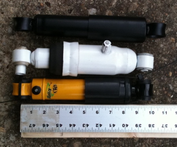
Damper Options
Premium adjustable dampers (e.g., Koni) will allow you to tune the car's handling characteristics. Some allow damping adjustments to be made in situ with the turn of a knob. Some front dampers have adjustable coil spring seats for changing ride height without changing the springs, making fine tuning of ride height simple and easy. As mentioned previously, it is best to use short bodied dampers on a lowered and stiffened setup to allow more bump travel than standard length dampers. Good front damper alternatives are ones that fit the Ford Mustang II, like the QA1 MS303 and the Pro Shocks ASBSR3AM2TP. These afford about 3 inches of total damper travel, i.e. about 6 inches of total front tire travel, divided roughly equally between bump and droop in the 1 inch lowered geometry. Another benefit of short bodied front dampers when used with springs as short as 9 inch free length is that the springs will not go slack at full droop.


As with front dampers, it is good to use short bodied dampers on a lowered rear suspension to afford more bump travel. Good alternatives are the non-adjustable Pro Shocks SM-401 and the adjustable Spax KSX series GDA4011SPAXLOW (offered specifically for lowered small chassis Triumphs). Both have about 8.75 inches compressed length vs. the typical standard 9.5 inches and nearly 4 inches of damper travel, i.e., about 6 inches of total rear tire travel.


When adjusting dampers, start by setting them to fully soft, then go through cycles of driving and adjusting until the handling is best/times are fastest. Here's how to adjust dampers that have single combined bump and rebound adjustment (adapted from Spax):
Initially set all dampers to fully soft. Then adjust up in four (4) click increments and drive. Every time the driving sensation improves, carry on adjusting up by four (4) clicks. Every time the driving sensation becomes worse, adjust down by one (1) click.
Here's how to adjust dampers that have separate bump and rebound adjustment (adapted from Koni):
COMPRESSION
(BUMP): Adjust bump damping first, before adjusting extension
(rebound)
STEP
1: Set all four dampers on minimum bump and minimum rebound settings.
STEP
2: Drive one or two laps to get the feel of the car. Note: When driving
the car during the bump adjustment phase, disregard body lean or roll
and concentrate solely on how the car feels over bumps. Also, try to
notice if the car "walks" or "side-hops" in a rough turn.
STEP
3: Increase the bump setting three (3) increments on all four dampers.
Drive the car one or two laps. Repeat this step until a point is
reached at which the car starts to feel hard over bumpy surfaces.
STEP
4: Back off the bump adjustment two (2) increments. Note: The back off
point will probably be reached sooner on one end of the vehicle than
the other. If this occurs, keep increasing the bump on the soft end
until it, too, feels hard, and then back it off two (2) increments.
Bump damping is now set.
EXTENSION
(REBOUND):Adjust rebound damping only after setting bump
damping
STEP 2: Increase rebound damping three (3) increments on all four dampers and drive the car one or two laps. Repeat this step until the car enters the turns smoothly (no drastic attitude changes) and without leaning excessively. An increase in the rebound stiffness beyond this point is unnecessary and may result in a loss of cornering power. Note: As with the bump settings, this point will probably be reached at one end of the car before the other, so keep adjusting the soft end until it feels smooth and does not lean too much. Rebound damping is now set.
Ensure Good Brakes (a.k.a., before you go, make sure you can STOP!)
The final segment here under handling is braking. Brakes are of course important for safety, but good braking is key to good handling and crucial to making a car faster if you want to do more than just go in a straight line. Besides, fast effective braking is fun! Braking is simply the conversion of the kinetic energy of motion into waste heat energy. Braking force is the product of the coefficient of friction of the braking material and caliper piston force, and piston force is proportional to total caliper piston area, so larger calipers with more total piston area and pads with higher coefficient of friction material will improve braking. Brake effectiveness is also dependent on the ability to eliminate or dump waste heat, so bigger rotors, vented rotors and larger pads will dissipate heat better and yield better braking with less fade. Spitfire brake components in good working order make for adequate braking, but there is a range of enhancement options to consider. The simplest and most significant change you can make for the better with the stock setup is to use premium brake pads. Mintex, Hawk and Porterfield brand pads are good upgrades. Another easy and relatively inexpensive upgrade is to replace the stock rubber flex lines with less complaint ones, typically covered in braided stainless steel. The stock flex lines connecting the hard lines on the frame to the brakes on the suspension swell a little bit under pressure. Replacing them with less compliant ones will transfer more braking force faster to the brakes, improving performance and feel. There are many alternative hardware options for further enhancing braking. One relatively easy and essentially bolt-on upgrade is to install GT6 brakes. GT6 caliper piston area, pad area and rotor area are all greater than that of Spitfire brakes. Swapping front brakes involves substituting GT6 vertical links, spindles, hubs, wheel bearings, rotors and calipers for the Spitfire parts (everything outboard of the A-arms); you can't substitute just rotors or calipers due to component compatibility. The rear drum brakes of the GT6 are larger too, and these parts can be substituted as well, but this is not as important and not absolutely necessary. Because the process of braking transfers weight to the front, the front brakes do most of the braking and are most important. Another, nearly bolt-on upgrade that is readily available and relatively inexpensive is to install GT6 hardware but use '79-83 Toyota pick-up truck front brake calipers (you can modify the following adaptation of Toyota brake calipers to TR Triumphs for fitment to the Spitfire). Make sure your wheels will accommodate the larger GT6 or Toyota calipers without interference. Lastly, there are several, albeit relatively expensive, aftermarket brake kit options using parts from manufacturers such as Alcon, AP and Wilwood that can significantly improve brake performance.
Handy metrics of braking capability are total swept area of braking surface and swept area per ton of vehicle weight. Typically the greater these values, the better the braking. The greater the swept area, the more fade resistant the brakes are likely to be, and the greater the swept area per ton, the shorter the braking distance is likely to be. Early Spitfires (Spitfire 4/mk1 and mk 2, which have 12P front calipers) have 199 sq. inches of total swept area (144 sq. inches front discs and 55 sq. inches rear drums) yielding around 249 sq. inches/ton. Later Spitfires (those with 14P calipers, i.e., mk3, mkIV and 1500) have 205 sq. inches of total swept area (150 sq. inches front discs and 55 sq. inches rear drums), yielding 248 sq. inches/ton (mk3) to 219 sq. inches/ton (late U.S. market 1500). For comparison, upgrading to GT6 brakes leads to 260 sq. inches swept area (197 sq. inches front discs and 63 sq. inches rear drums) and makes possible 325 sq. inches/ton on the earliest Spitfires (31 percent increase) to 277 sq. inches/ton on the late U.S. market Spitfire 1500 (27 percent increase). The results are summarized in the following table:

 data")
For
more insight and information on vehicle handling and suspension
design, check out:
How to Make Your Car Handle, by Fred Puhn
Tune to Win, By Carroll Smith
Power = Torque * angular velocity [note: this is a scalar product]
= Torque * 2*pi * rotational speed
When using the Imperial units foot-pounds for torque and horsepower for power, and using RPM (revolutions per minute) for rotational speed, the equation becomes:
hp = ft-lbs * RPM/5252
In the SI units of Newton-meters for torque and kilowatts (kW) for power, this becomes:
kW = N-m * RPM/9549
Other handy relationships are:
1 hp = 746 watts, 1 kW = 1.341 hp: multiply hp by 0.7457 to get kW; multiply kW by 1.341 to get hp
1 ft-lb = 1.356 N-m, 1 N-m = 0.7376 ft-lbs: multiply ft-lbs by 1.356 to get N-m; multiply N-m by 0.7376 to get ft-lbs
1 RPM = 1/60th Hz; 1 Hz = 60 RPM: 6000 RPM = 100 revs per sec (100 Hz) = 1 rev every 10 milliseconds = 36 crank degrees per millisecond

Spitfires came with basically four different engines--all variations on the same Standard-Triumph model inline-four, three main-bearing, pushrod-actuated overhead valve engine. Spitfire 4, mk1 and mk2 models came with 1147cc displacement units, mk3 and mkIV models came with two versions of the 1296cc or "1300" engine (the "small journal" models in the mk3 and "large journal" in the mkIV) that are basically bored-out versions of the 1147, and the 1500 came with the 1493cc or "1500" engine, which is essentially a stroked large journal 1300. There is further differentiation through the use of different cylinder heads and camshafts. The 1147 and small journal 1296cc engines have the lightest crankshafts and can spin up to the highest RPMs, and the small journal 1296 is popular with racers. The large journal 1300 and especially the 1500 have the heaviest cranks and flywheels of the bunch and so don't lend themselves to running as high RPMs as the small journal engines. However, the 1500, being longer stroke, produces more low RPM torque and is a perfectly adequate engine for a street Spitfire.
The purpose of the drivetrain is to apply torque from the engine to the drive wheels and tires. Unlike DC electric motors, which develop max torque at zero RPM that decreases from there, internal combustion engines produce max torque at a mid level of RPM and produce reasonable levels of usable torque over a range of RPM, so some gearing is a good idea. Gearing simply is a way to apply different amounts of leverage to make the most use of the torque and power from the engine to make the car move effectively. Gearing "transforms" torque, but not power. A 'low' gear, like the 3.75:1 first gear in a Spitfire mk3, multiplies the torque from the engine 3.75 times but reduces the speed of rotation 3.75 times (divides by 3.75) and so power is unchanged (neglecting frictional losses). The final drive multiplies torque again, by 4.11 in the Spitfire mk3, to deliver it to the wheels and tires for application to the ground. The 'low' gear (high leverage ratio) allows the engine to rev up quickly and operate near peak power where it can deliver a lot of torque most quickly and do the most work with the car at zero or low speeds. As vehicle speed increases, the gears are changed to higher ones (lower ratios) to allow the engine to continue to work at high revs where its power is greatest and it can make the car accelerate as much as possible. The ratios and "spacing" of the transmission gears and final drive, the strength of all the elements and frictional losses in the drivetrain are also important factors determining quickness and reliability.
If you are planning on using your Spitfire for a lot of highway driving, consider installing a transmission with an 'overdrive' unit or replacing it with a 5-speed transmission adapted from another vehicle (e.g., a Ford T-9) in order to have a top gear with a ratio of less than 1 to keep the cruising RPM down and reduce engine wear over time. Using a 3.89:1 final drive with an overdrive is a nice combination for street use that provides both quickness and reasonable RPMs for highway cruising. There's a weight penalty of about 26 pounds with an overdrive unit compared to no overdrive, but it's a fair trade. If you use a 4.11:1 final drive, the differential assembly in the late (FC120001 and on) Spitfire mk3 and 1972 North American Spitfire mkIV is the most robust with the same "large" output stub axles as those in the later 3.89:1, 3.63:1 and 3.27:1 units. These later final drives are the strongest, possessing the largest and strongest flanges, bearings and shafts all around.
The following equations relate road speed, engine RPM, gear ratio, final drive ratio and tire diameter:
vehicle speed (mph) = RPM*tire diameter (inches)/[336.1*gear ratio*final drive ratio], or
vehicle speed (kph) = RPM*tire diameter (cm)/[530.5*gear ratio*final drive ratio]
RPM = vehicle speed (mph)*336.1*gear ratio*final drive ratio/tire diameter (inches), or
RPM = vehicle speed (kph)*530.5*gear ratio*final drive ratio/tire diameter (cm)
James Carruthers has a nice gearing calculator on his "Mintylamb" site for comparing road speed and engine RPM for various gear ratios, final drive ratios and tire diameters.
Lose
Weight, i.e., "Add Lightness"
Many motorcycles can out-accelerate the hottest performance cars, even though they have much less power because proportionally they weigh even less such that the ratio of their power to their weight is much higher than that of most cars. The easiest and cheapest way to make your Spitfire feel more powerful is to shed mass and improve the power-to-weight ratio. As mentioned earlier under handling, this is easy to do on the later Spitfires in the U.S. by removing all the extra bumper and bumper reinforcing hardware they were burdened with.
A good metric of performance is power per unit mass (or weight). Horsepower at the wheels divided by total test weight of the car is the ideal metric, but since wheel horsepower is typically not published information and has to be obtained on something like a rolling road that introduces additional variables, peak brake horsepower (bhp) is a good proxy for relative comparison purposes. Below is a plot of actual test data of Spitfires (from "Triumph Spitfire Gold Portfolio") and some assorted vehicles circa 2011 (from "Road & Track" test reports) spanning the range, from the 70 bhp Smart fortwo coupe to the 1001 bhp Bugatti Veyron Grand Sport supercar, plus the 119 bhp Ducati 848 EVO motorcycle for comparison. The trendline is a best-fit of the actual data (weights are as-tested and include driver weight), and given the mathematical relationship it is a straight line on a log-log plot. The point of the plot is to illustrate the relationship between acceleration and the power-to-weight ratio. The greater the power-to-weight ratio, the quicker the vehicle; each doubling of bhp/ton cuts acceleration time approximately in half:

"Adding lightness" is very high return for lower bhp/ton cars like factory-spec Spitfires. Note that driver weight is a larger proportion of total test weight for lighter cars. In the case of a Spitfire, the weight of the typical driver is around 10 percent of the car's weight so the driver's weight has a bigger effect on a Spitfire's performance than it does on a heavier car like a Ford Mustang. Having a passenger or some cargo aboard your Spitfire will noticeably reduce acceleration. Besides shedding vehicle weight, shedding driver weight is something to consider! This underscores why horse jockeys are small, and why minimum weight constraints exist for horse racing and auto racing. For a typical Spitfire, a reduction of 25 to 30 pounds is equivalent to adding one horsepower (not counting other benefits). Roughly speaking, increasing Spitfire engine peak power to 90 bhp and beyond (i.e., 1 bhp or more per cubic inch displacement) enables crossing the 100 bhp/ton, 10 second 0-60 threshold. Clearly, you can take your Spitfire's quickness from pathetic to acceptable by increasing bhp/ton by losing weight and adding power.
The
following is basically about better breathing to get the
fuel and air into and the exhaust gases out of the engine more
effectively (carbs,
exhaust, head
work, cam), and increasing the engine's thermodynamic efficiency so as
to
better convert the potential chemical energy of the fuel+air charge
into
kinetic energy (ignition timing, higher compression).
Ignition timing is critical to Otto cycle engine performance. Why? For best performance, maximum pressure developed by the burning mixture in a cylinder should occur a little after the piston has passed top dead center (TDC) and is on its way back down the cylinder to take advantage of the mechanical leverage of the position of the piston connecting rods and the crankshaft and optimally develop torque. Developing pressure too early or too late wastes performance potential, and in the extreme can lead to damage. But it takes a finite amount of time for the combustion, initiated by the spark, to propagate throughout the mixture in the cylinder. Pressure, temperature, motion of the mixture and fuel grade all affect combustion speed--pressure being the most important factor. To account for the finite amount of time it takes combustion to occur and for max pressure of combustion to be reached at the optimum position of the piston, the spark needs to be "advanced," typically to occur some number of degrees before the piston reaches TDC. As engine speed increases, the speed of combustion doesn't increase as fast as the engine, so progressive spark advance is needed to keep the max pressure of combustion occurring at the right time. This is true to first order up to a point, because as engine speed (RPM) increases, pre-combustion cylinder pressure (up to the limits of the engine's induction system to flow mixture), mixture motion and fuel atomization increase too, and these things speed-up combustion. Beyond around 3000 to 4000 RPM in most engines, these effects keep pace and so no further advance is needed. Finally, the amount of load on the engine affects optimum spark timing. Less advance is needed when accelerating, with the throttle wide-open and lots of air is cramming into the engine and raising absolute pressures inside it, as opposed to when cruising or decelerating and pressures are reduced. Therefore, at a given RPM, more advance is needed at low engine loads (i.e., low absolute manifold pressures).
As
you progress with engine modifications, the
best
amount of total ignition advance for
a given engine speed and load changes, so to fully
reap the benefits of engine performance modifications, it pays to
revisit your ignition timing when making performance changes. For
example, as you raise an engine's compression, less advance is needed
at a given engine speed, and you want to be careful not to have so
much advance that you encourage detonation
(a.k.a., knock, pinging, pinking). If you go with a "bigger" cam,
volumetric
efficiency and dynamic compression are reduced at low RPM but increased
at high RPM, thereby reducing combustion speed at low RPM but
increasing it at high RPM and requiring an ignition map with a
different shape and a steeper "slope" (camshafts are discussed later in
this article). So to get the most out of a
given camshaft and overall intake setup, ignition timing is crucial to
preserving low RPM behavior and maximizing high RPM performance. "More"
is not "better" when it comes to advance. Don't be fooled by an
ignition map with big advance numbers everywhere. Proper spark timing
is about optimizing performance for a given engine
configuration.
Until
recently and before the advent of electronics, spark timing on most
Otto cycle engines has historically been determined and controlled by
the distributor. Static advance is set by the position of the
distributor such that the rotor and plug wire electrodes in the
distributor cap are aligned relative to piston position at rest as
desired (e.g., to set timing at idle). Dynamic advance with a
distributor is accomplished via two mechanisms--centrifugal and vacuum.
Centrifugal advance adjusts spark timing as a function of engine speed
and works this way: little weights constrained by little springs inside
the distributor fling outwards more and more as the distributor spins
faster and faster with increasing engine speed, up to a limit imposed
by pins or some other hard stop. The stiffness of the springs and the
mass of the weights controls how far the weights move for a given
speed. The outward motion of the little weights rotates a plate that
holds the spark triggering mechanism (e.g., a cam actuating contact
points, or a multi-pole magnet interacting with a Hall effect sensor,
or
a chopper wheel interrupting the light path between a light source and
an optical sensor, all of which function as switches to interrupt
current flowing in the primary winding of the coil and resulting in
magnetic field collapse and induction of high voltage in the secondary
winding of the coil). Vacuum advance (or sometimes retard) adjusts
spark timing as a function of engine load, where vacuum in the intake
system is used as a measure of engine load (e.g., cruising,
accelerating or decelerating). Vacuum can be sensed via a tap or
multiple taps on the intake manifold, or a port near the throttle
plate. A vacuum line goes from the intake vacuum tap to a vacuum
canister on the distributor containing a diaphragm, and the diaphragm
is attached to a link that is attached to the plate holding the spark
trigger mechanism, so motion of the diaphragm, in response to intake
vacuum, can advance (or on some distributors, retard) the spark.
Convert
from Points to Electronically-Triggered Ignition, or to
Fully-Electronic Ignition
Something to consider is making the switch from a mechanical spark trigger (points) to an electronic spark trigger (Hall effect (magnetic) or optical trigger), i.e., electronically-triggered ignition. The Pertronix series of products are easy, reliable drop-in replacements that take the place of points in your distributor. Switching from points to electronic ignition can enhance performance and will reduce maintenance and improve reliability.
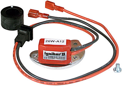
A worthwhile modification to make, especially if you make other engine mods, is to eliminate the distributor and replace its function with a fully-electronic ignition control system like MegaJolt or the ignition portion of the MegaSquirt fuel management system. These systems, which sense engine position using a toothed "trigger" wheel attached to the crankshaft pulley rather than the shaft of the distributor, enable precise and fully-programmable ignition advance settings vs. engine speed and load. These are a bit more involved than simply replacing the points assembly in the distributor with a little electronics module, but they work well and have a large user community, so support is readily available. I installed MegaJolt on my modified '78 Spitfire 1500 and I'm thrilled with it.
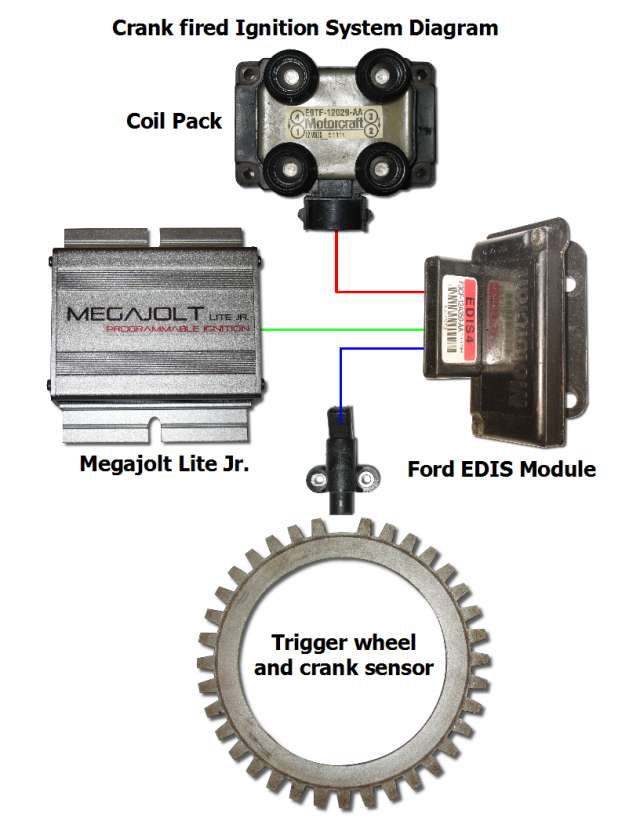
So, why not stick with a distributor instead of going with a fully-electronic, programmable system for controlling ignition timing? Two main reasons. First, changing the advance map on a distributor is very difficult, time consuming and not really deterministic. It involves adding (welding on) or subtracting (grinding off) mass from the centrifugal weights, changing the centrifugal weight springs, and changing the range of motion that the vacuum/retard mechanism makes or imparts to the distributor. Being able to simply change spark timing incrementally at the click of a mouse, as with MegaJolt, is completely deterministic, much faster and allows results to be assessed immediately before environmental conditions change that can affect interpretation of results (like air temperature, humidity, etc.). Moreover, ignition timing maps can be implemented that simply are not physically possible to create with a mechanical system (if such a thing is warranted). Second, fully-electronic systems like MegaJolt eliminate several mechanical interfaces involved in communicating piston position and delivering the spark that add uncertainty and reduce precision in spark timing. In a traditional distributor-equipped engine, the crankshaft turns the camshaft through a chain or belt, and the camshaft incorporates a gear that engages and turns the distributor shaft, which actuates the centrifugal advance weights and springs that actuates a mechanism for interrupting primary current to the coil as well as turns a rotor that spins past contacts in the distributor cap to distribute spark to each spark plug. In the case of many fully-electronic ignition schemes, piston position is sensed directly off the crankshaft by the variable reluctance sensor "looking at" the toothed wheel and all spark triggering, switching and distributing is done purely electronically, and so the timing "slop" contributed by the rest of the mechanical interfaces in a conventional distributor-based ignition system are eliminated, thereby resulting in much more precise timing and virtually eliminating jitter. Lastly, all-electronic ignition systems sense engine load, via a measure of manifold pressure using a pressure transducer or throttle position via a potentiometer, more accurately than a vacuum diaphragm attached to a distributor plate carrying spark triggering components.
If
you want to retain a distributor and still have the advantage of
electronically-selectable alternative advance curves, a good
aftermarket option is 123Ignition. Standard 123Ignition
distributors have 16 different preset curves to choose from, and there
is a line of programmable distributors that afford further
customization. 123Ignition is a nice, simple drop-in alternative to
systems like MegaJolt and MegaSquirt.
Better breathing is about making it easier for gases to get in
and get out of the engine and it can cost some money, but the expense
is not unreasonable for the corresponding improvement in performance
and many
of the following enhancements are relatively easy to make, so they fit
the theme of this article.
Install
a Better Exhaust Manifold or Header
The
purpose of the exhaust system is to enable the evacuation and
scavenging of waste exhaust gases and even aid the intake of the next
cycle's fresh air+fuel mixture. When an exhaust valve opens, a
compression wave of acoustic energy rushes from the valve, out of the
head and down the manifold or header tube at the speed of sound, which
is about 1700 feet per second (roughly 20 inches or 50 cm per
millisecond) at such temperature. The actual exhaust gas follows behind
as a chunk of mass moving at a subsonic speed of about 300 feet per
second (roughly 3.6 inches or 9 cm per millisecond)--about five times
slower than the acoustic pressure wave ahead of it. The moving mass of
exhaust gas leaves behind a wake of low pressure as it moves along, and
this low pressure helps suck gas from the cylinder. This is inertial
pumping. When the faster-moving acoustic pressure wave reaches a
transition where it experiences a sudden expansion, like at a collector
where exhaust tubes from other cylinders join together, part of the
acoustic compression wave continues down the exhaust system but part of
it is reflected back up the same manifold tube as an expansion or low
pressure wave. If this reflected low pressure wave reaches the exhaust
valve late in its cycle while it is still open and when the intake
valve is also open early in its cycle, i.e., during valve overlap, then
it will reduce the pressure inside the cylinder, which will not only
extract remaining exhaust gas from the cylinder but also suck fresh
air+fuel mixture into the cylinder. This is acoustic pumping. A
performance exhaust system is designed to make use of both inertial and
acoustic pumping to improve the engine's volumetric efficiency and
increase performance.
An exhaust manifold or header is sort of like a tuned musical
instrument. Pipe lengths and diameters determine its 'tune'. Longer
pipes mean longer travel times, resulting in more torque at low engine
speeds below the torque peak but less torque at high engine
speeds above the torque peak. Larger diameter pipes mean slower gas
flow (longer travel times) but less backpressure and reduced pressure
loss with pipe length, shifting where peak torque occurs to higher
engine speeds. Thermally-insulated pipes keep heat in the exhaust for
higher exhaust gas
temperatures, which means faster gas flow (but also a benefit
in reduced intake temperatures for improved volumetric efficiency).
Collector sizes and shapes are also important to header performance in
that they influence the strength of the reflected low pressure acoustic
wave and affect the way the pulses of exhaust gas blend and flow
together.
The stock manifold on the later U.S. Spitfires has tubes so short that
beneficial acoustic scavenging never really happens within the
operating RPM range of the 1500 engine, although they are do allow gas
flows to combine so as to at least not interfere with each other and
enable some degree of inertial pumping. Almost any header can help a
later Spitfire's performance simply by enabling smoother flow and
delaying the timing of acoustic pumping,
but a properly tuned header of good design and workmanship can
significantly improve performance by optimally timing acoustic pumping
to really harness it.
For four-cylinder engines like the Spitfire's, there are 4 into 1
headers in which all the pipes collect together at once (like the stock
U.S. spec 1500 manifold, only much longer; see image on left below),
and 4 into 2 into 1, or Tri-Y systems in which pairs of pipes for
cylinders with exhaust strokes 360 crank degrees (180 distributor
degrees) apart collect together first to form a single pair of pipes
that later collect into one. Collecting pairs of pipes that aren't
separated by 180 distributor degrees would degrade performance because
their
exhaust valve openings would overlap and gas flows would collide
instead of meshing and one primary would pressurize the
other, thus impeding flow. For the 1-3-4-2 firing order of the Spitfire
and
most other inline four-cylinder engines, #1 and #4 cylinders collect
and #2 and #3 cylinders collect together. These first pipes leaving the
head are called primaries, and the second ones after the merging of
primaries are called secondaries.


For street use, the 4-2-1 systems are best because they provide
improved performance in the middle range and over a broader range of
RPMs, even though they typically don't produce as much peak power as
4-1 systems. 4-2-1 systems 'play a chord' and have broader torque
curves with more mid-range performance than 4-1 systems, which 'play
one note' and produce more high-end torque and peak power.
Four-cylinder race cars often use 4-1 systems because their engines
spend basically their whole time operating at high RPMs at or around
the peak power point, and maximum power is more important than broad
power or power in the low and middle range.
Note that for inline six-cylinder engines, like the GT6 2-liter, there
are two ways to have a 'compound' header like the 4-2-1: the 6-2-1 (two
sets of three primary pipes gathering into two secondary pipes that
gather into one) and the 6-3-1 (three pairs of two primary pipes
gathering into three secondary pipes gathering into one). By far the
better performing configuration is the 6-3-1. It combines pairs of
pipes from cylinders with exhaust strokes that are 360 crank degrees
(180 distributor degrees) apart and thus one exhaust valve is
closed while the other is open and the operation is bascially
the same as that described above for the
4-2-1 configuration. The Triumph inline six firing order is
1-5-3-6-2-4, so the correct way to gather primaries is 1+6, 5+2 and
3+4. Contrast this with the usual 6-2-1 configuration where cylinders
1, 2 and 3 are gathered and 4, 5 and 6 are gathered, all cylinders that
are only 120 distributor degrees apart so exhaust
valve openings overlap and backpressure is an issue.
In V8s, cylinders are usually combined like two separate four cylinder
systems. This is easy to implement for single-plane crank V8s because
each side of the engine is configured like a single inline 4 cylinder
so all cylinders on the same side of the engine easily combine as
4-1 or even 4-2-1. However, correct pairing of cylinders on
cross-plane crank V8s is not so easy because ideally two cylinders from
each side need to combine, so a practical alternative is to configure
like two 4-1 sets of pipes connected by a balance pipe.
For more information about exhaust tuning theory and practice, see:
Exhaust Science Demystified, by David Vizard, from Popular Hot Rodding (February 2009)
How Headers Work, from Super Chevy (February 2009)
Four-Stroke
Performance Tuning in Theory and Practice, by A. Graham Bell
Install
Freer-Flowing Air Filters
K&N
air filters are proven to flow more air than standard
paper elements, and are sometimes even better than no filter. Some folks think they look
nice
too. You'll
probably have to
retune your carbs after installing K&Ns.
Install
Short Air Horns on the Carbs
This
will provide a smoother path for air to get into your
carb(s). Short
ones, called
stub-stacks, will help performance a little yet still fit inside your
air
filters. Like the
principle behind
exhaust runner lengths above, air horns (sometimes called ram pipes)
can help
air enter the engine through tuning of inertial flow, and the longer
the intake air horns are, the
lower the
RPM at which the ram effect occurs. Stub
stacks are too short to tune the ram effect very much, but
they do provide a radiused entry for air to go into the carb(s), which
smooths
airflow and does help performance a little.
Install
Better Intake Manifolding and Carburetors
While
the single Zenith-Stromberg (Z-S) carb that came on the 1500
engines for the US market isn't bad, the manifold between it and the
cylinder head has
two abrupt
right-angle turns in it. This 'log' manifold works, but a more direct
path from carb to head can improve flow. Moreover,
the ports of the US market Z-S log manifold are smaller that the ports
on the cylinder head, so they are not matched. But
changing just the
manifold isn't
really an option for the Zenith-Stromberg setup, so a good alternative
is to install twin Skinners Union (SU) HS2
or
HS4 model carburetors
and a matching ram-style intake manifold like what the 1500s for other
markets
got from the
factory. The
twin SU setup in which one carb feeds two cylinders allows for a nice
straight-through flow of the air and fuel mixture into the cylinders. The earlier US market
Spitfire 1300s have
this twin
carb arrangement using HS2s, and this is a simple bolt-on upgrade from
the single
Zenith-Stromberg
configuration. HS2s will work
fine on a 1500, while HS4s will perform better than HS2s at high RPM on
modified engines. Used
SU carb and
manifold assemblies are available from many suppliers for not too much
money. New SU carbs
are available
too (manufactured by Burlen
Fuel Systems) but they are more expensive
than used
ones. You'll
need
to figure out
what needles and dashpot springs to use too, which will depend on the
engine's
state of preparation and your altitude and general climate conditions.
For suggested SU needles for various stages of tune, see the
"stages of improvement" section near the end of this article.
")
You can also try other carbs, like Weber or Dellorto side-draught carbs instead of SUs. These are more expensive, but they are capable of terrific performance.

At this point, the way to improve breathing is to focus on modifying the cylinder head to get it to flow better. This can get expensive, but some minor mods involving simply matching the ports of the cylinder head and the manifold and removing any irregularities in the ports that might disturb airflow are easy and inexpensive to do and will help performance if done correctly.
"Port and Polish" and "Flow" the Head
The capability of the cylinder head to flow gases and promote good combustion has enormous bearing on the engine's ability to generate power. People with much experience at wringing power out of engines have empirically determined the modifications that improve flow in cylinder heads to significantly improve performance, and some of this knowledge has been captured in various publications (e.g., Bell, Vizard). You can pay a professional to make head mods or you can try some of the more pedestrian ones yourself.
On intakes, it's good to match the head ports and the manifold ports. You don't want to enlarge them, just match them so that there's no step and the transition from manifold to head is virtually seamless. On exhaust ports, almost the opposite is best for performance. Empirical evidence indicates that a step from the head exhaust port to a slightly larger manifold port/header pipe is good. It reduces exhaust backflow and helps acoustic scavenging. Therefore, don't try to match exhaust head and manifold ports. However, do make sure there are no locations where the manifold ports are inside of/smaller than the head ports so as to protrude into the flow leaving the head.

Care must be taken when modifying the port runners in the head between the mainfold ports and the valves. Don't significantly alter the shape or size of the port runners, but rather remove sharp edges and transitions within the port runners that can disrupt flow. Just some modest grinding and polishing to clean-up leftover casting and machining irregularities and eliminate sharp transition areas is good. Often there is a little sharp edge just before the valve seats left over from casting and/or installation of the valve seats, particularly on the short radius side. Grind away the sharp edge and make a nice smooth transition while keeping a nice radius. It's also good to smooth the areas around the valve guides, but you don't need to remove a bunch of material here. You want to have a little bit of a venturi shape behind the valve seats; ideally a valve port throat that is about 90% of the valve diameter is good. Be careful not to get carried away and grind too much. Do not simply enlarge the port runners everywhere or you'll make flow worse. Tapered valve guides help reduce obstruction to flow too.

Also, it's beneficial to have flow that enters each chamber with some curve or swirl to it so that as the compression stroke occurs and the mixture gets 'squished' it mixes rapidly and well, which is conducive to good propagation of the combustion flame front from the spark plug to all reaches of the mixture in the combustion chamber. There is often a noticeable step between the machining left over from port drilling and the cast portion of the intake port runners in Spitfire 1300 and 1500 heads. Grind this to seamlessly blend them together. Rounding-off the little sharp edges of the bevel near the spark plug hole can help gas enter and exit the cylinder but it can let the curl of the swirl open-up, so it's a balancing act there. Don't degrade swirl by grinding away on the inboard side wall of the port runners except to blend discontinuities, and beware the little bump in the outer wall of the exhaust port runner near the exit--it's close to a stud hole.

What matters is flow through the head as it will be operating--with valves installed and open to varying degrees. You can achieve big flow through a head with wantonly enlarged runners and no valves installed, but that's not the operating configuration of the head and such flow numbers are misleading and will not be representative of the head in actual operation. Besides, flow quantity is only part of the story--high flow alone doesn't directly translate into more torque and power. Proper, efficient flow into and out of the cylinders with the valves present is what counts. Flow around valves in heads that have rather asymmetrical port flow like the Spitfire's will be improved by shaping the backsides of the valves to be less 'tulip' shaped and more 'nail head' shaped. A backside radius of about 0.2 times the valve diameter is about optimum for heads with asymmetrical port runners and 'bathtub' shaped combustion chambers like the Spitfire's (stock radius ratio is 0.25 to 0.3). Getting rid of that first ridge where the single stock valve grind meets the backside with a multi-angle grind helps flow around the valve, even if you choose not to tighten the radius on the backside. A multi-angle grind on the valve seats helps too, producing a nicely radiused venturi while ensuring adequate seat contact for good sealing and heat transfer (crucial for conducting heat from the exhaust valves to the head and coolant).

There are limits to what can be done to 'unshroud' the valves in Spitfire heads to further aid flow because the valves are very close to the walls of the combustion chamber recesses, and these recesses already reach out to and line up with the edges of the cylinders. But, if there is any difference (perhaps from boring the cylinders), then a little relief to the walls of the combustion chamber to unshroud the valves can help. As mentioned above, some rounding-over of the sharp edges of the beveled step near the spark plugs will serve to unshroud the valves some and improve flow into and out of the cylinders. Intake valves appear to benefit more by unshrouding than do exhaust valves.

Be sure to make the same mods from cylinder to cylinder and measure the volume of each of the combustion chamber recesses in the head. Perform any minor rework necessary to equalize all the volumes to within 0.2cc or less. Be sure to base any compression ratio calculations and planned adjustments (e.g., head shaving) on these measured values.

For
more insight here, check out these references:
Four-Stroke Performance Tuning in Theory and Practice, by A. Graham Bell
Tuning Standard Triumphs Over 1300 cc, by David Vizard
Theory and Practice of Cylinder Head Modification, by David Vizard, et al.
How to Build, Modify & Power Tune Cylinder Heads, by Burgess and Gollan
Triumph Competition Preparation Manual
One
last thing that fits under improved breathing is the
camshaft. Changing
the camshaft in
most Spitfires can help, but only after other things have been done,
like
improving the exhaust and intake and head flow, and especially raising
the static
compression
ratio of the engine, which is described next.
Increasing
compression increases the efficiency of the
thermodynamic cycle of the engine, which yields more torque and more
power. Static
compression
ratio is simply
the ratio of the volume above a piston when the piston is all the way
down at
bottom of its stroke (bottom dead center, or BDC) to the volume above a
piston
when the piston is all the way at the top of its stroke (top dead
center, or
TDC). If you think
of the volume
left when the piston is at TDC as Vcc (combustion chamber volume) and
the volume swept by the
piston as Vd (cylinder displacement volume),
then the volume above the piston at BDC is Vd+Vcc and the compression
ratio CR
= (Vd+Vcc)/Vcc.

Vcc includes not only the volume of the recess in the cylinder head, but also the volume of the gap determined by the head gasket's thickness, the volume of the cavity in the top of a dished piston (or the negative volume of the space taken by a crowned piston) and what little other volume that might remain between the piston and the top surface of the block at TDC ("deck volume") or in the little gap between the piston and the cylinder wall and above the top ring (negligible for practical purposes). For Spitfire 1300 and 1500 engines, gasket volumes and deck volumes are all the same, so compression ratio is determined by the head volume and the piston type (dished or flat). On a Spitfire 1500 with 7.5:1 static compression ratio, as all North American models were (except 1976 models, which had 9:1 static compression), changing the pistons from the stock dished ones to flat-top ones will reduce Vcc by the volume of the dished space, which is about 6.7 cubic centimeters per cylinder, and thus raise compression to nearly 8.4:1. This helps performance some. You can raise compression further by substituting a compatible head with smaller combustion chambers and/or shaving/milling material off of the head surface to shrink combustion chambers. However, increasing compression increases combustion pressures and temperatures and elevates the likelihood of detonation and detonation-induced pre-ignition, which can damage or destroy pistons. A static compression ratio of 9.5:1 or 9.75:1 is the practical limit for a Spitfire street engine with a reasonable cam profile running on contemporary pump gasoline. More modern cars sometimes have higher compression ratios, but that's because they employ knock-sensing systems that dynamically adjust (retard) the ignition to avoid prolonged detonation. Race engines typically have very high static compression ratios, but they also have more aggressive camshafts with very long valve opening duration and overlap, which reduces the effective or real compression inside an engine while it is operating. Racing competition and the overarching objective of winning a race typically favors peak power over long-term reliability and low or moderate-speed driveability and justifies spending more for special, tougher materials (e.g., forged instead of cast pistons), frequent engine rebuild or swaps, and other expensive and time-consuming things.
Raising compression on a Spitfire, by
swapping and/or shaving heads and switching pistons, will help
performance. Changing
pistons isn't
too difficult but new pistons are moderately expensive. Swapping
or shaving a cylinder head
is easier and can be less expensive. Removing
the cylinder head isn't too tough a task, and
once you have it
out of the car, a good machine shop can quickly remove the
amount you
desire for a very modest fee. I've
constructed a compression
ratio calculator spreadsheet
that you can use to figure out how much you need to shave off a given
head to reach a
desired static compression ratio. I've
also compiled information about interchangeable cylinder heads for
Triumph 1300 and 1500 four-cylinder engines (see table below--still a
work in progress) that can
be used in conjunction with the compression calculator to generate
various engine configurations and compression ratios.
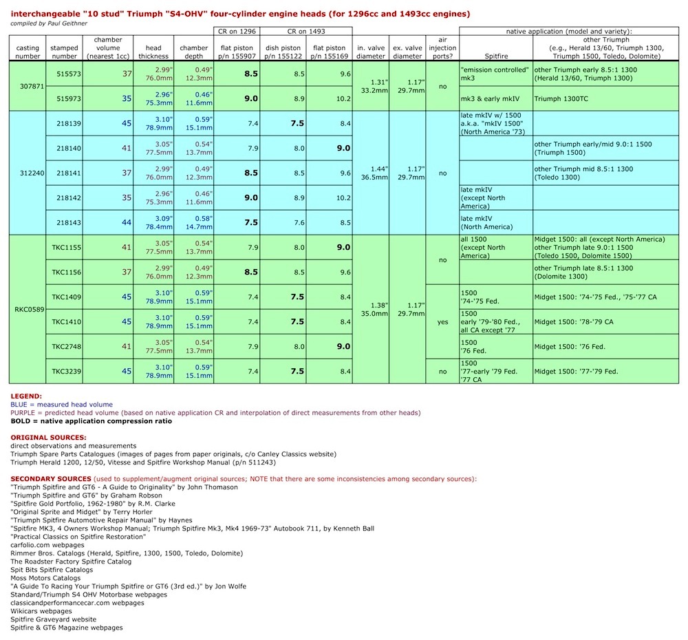
Triumph
1300 and 1500 heads are interchangeable, and evidently were made in
three castings (identified by
different cast-in numbers) that in turn were machined different amounts
to yield different combustion chamber sizes (stamped with
different part numbers) for various car models for different
markets around the world. All three castings accommodated valve seats
for the same size exhaust valves, but different size inlet valves. Note
that the hot ticket for the North
American market "low compression" 7.5:1 1500 with dished pistons is to
fit one of the "big inlet valve" heads, use either dished or
flat pistons, and perhaps do some shaving of the head. The bigger
inlet valves will support greater airflow and permit higher performance
to be extracted from more extensive mods (like a bigger cam). For
example, nearly
9:1 compression can be achieved on
a "low compression" dished piston short block
by simply installing a stock 218142 head from a world market (non-North
American) late Spitfire mkIV (FH25001 and later). A little shaving of
this head (about 0.040 inches or 1mm) before you install it and you'll
have a 9.5:1 engine with big inlet valves and without taking anything
apart in the bottom end. Or, take a head from a Toledo 1300 (part
number 218141) and put it on a 1500 with flat-top pistons and get about
9.6:1. Some "big inlet valve" heads came in North American market cars,
and these can be shaved and used with flat-top pistons to get the same
result. Another option for the "low compression" 1500 is to replace
the
dished
pistons with flat-top ones and shave about 0.080" off the "low
compression" head it came with to produce an engine with a static
compression
ratio
of about 9.5:1. Note that merely changing from dished to flat-top
pistons in this instance will not result in 9:1 but rather 8.4:1
because the 9:1 1500 configuration also uses different heads (e.g.,
TKC1155 and TKC2748) that have smaller combustion chambers. 1500's
that started out as 9:1 engines can benefit from "big inlet valve"
heads and/or shaving to raise compression too. 1300
engines, particularly the more robust "small journal" ones popular with
racers, can be similarly upgraded by substituting shaved
versions
of one of the "medium" or "big inlet valve" heads. All of the above
heads are interchangeable on 1300 and 1500 blocks, so beware of
certain "bad" head, block and piston combinations that either raise
compression too much for typical street use or result in a downsizing
of inlet valves.
If you have an engine with raised static compression and improved flow characteristics, then it's possible to take advantage of a more aggressive camshaft (i.e., more valve lift and longer valve opening duration and overlap). The air+fuel mixture has inertia of course, so opening valves earlier and closing them later (i.e., increasing duration) enables more mixture to get into the cylinders at higher engine speeds, thus improving volumetric efficiency and increasing power at high RPM. The trade-off is that longer duration and overlap (principally later intake valve closing) dilutes pressure at low engine speeds and lowers the effective compression ratio, reducing torque and power at low RPM. So, choosing a camshaft for a fixed valve timing engine is a compromise between increasing performance at high RPM and decreasing performance at low RPM.


Reground
cams, which are
ordinary/stock cams machined to have a new profile, are less expensive
than virgin ones,
but be aware of material and surface finish choices and compatibility. You'll need resurfaced or
new tappets and
maybe shorter valve guides and different valve springs too,
depending on cam profile particulars. There
are many aftermarket Spitfire
camshafts to choose from, and manufacturers/vendors only
reveal certain
data about their cams (exact profiles are usually closely-guarded), so
choosing
among them can be difficult. To
first order, don't
get too aggressive with duration or overlap or your engine will not
perform
well at low RPMs and you may be disappointed in the way it behaves
driving it around in normal use. Furthermore,
increased valve lift beyond a certain amount will not add to
performance
because
of the limitations of the head to flow gases.
According to Dmitri Elgin, valve lift greater than
about
0.380"
in a Triumph engine will yield diminishing returns unless some flow
improvements have been
made to the head and valves. However, this is not to say
that a cam that generates peak lift greater than 0.380" is wasteful.
This is because valve velocity
and acceleration
are important too. A cam that has a fast 'ramp' will open the valves
more quickly and allow the valves to be more open more often and thus
capable of more flow. But, if the change
in cam ramp is too abrupt, then valve acceleration will be too high,
generating excessive forces on the valve train. A way to get sooner and
quicker valve openings and later and quicker valve closings without
excessive acceleration is to have a cam with a higher peak lift than
the
optimal max opening. Obviously, cams and valve operation are more
complicated than just duration, overlap and peak lift.
If you are not sure what to pick, be conservative and don't over-cam. The objective is to achieve a compatible match between compression ratio, cam duration, overlap and lift, and the flow characteristics of the head, intake and exhaust, while keeping drivetrain forces within design limits. As a rough guide for sporty street use, keep duration under 280 degrees or so and valve overlap under 60 degrees or thereabouts so that adequate performance at low RPMs is preserved and good performance in the mid-range is achievable. These guidelines are not hard and fast rules because many factors determine camshaft performance, and it is assumed that you have raised the static compression ratio and have installed good-flowing exhaust and intake parts, the specifics of which affect camshaft selection.
Actually, the Triumph factory 270 degree duration (25-65-65-25) cam that was stock in many of the 1300 engines is a really nice street cam. Be advised that this cam and the other early "small journal" cams ran in bearings installed in the block, while the later 1300 and all 1500 engines had "large journal" cams that ran right in the block without camshaft bearings. You can use a small journal cam in a late block as long as you install cam bearings.
For
more on camshaft
terminology, theory and practice, check out these references:
Four-Stroke
Performance Tuning in Theory and Practice, by A. Graham Bell
Camshaft
Glossary (Elgin Cams)
Camshaft
Theory (Second Chance Garage)
Performance
Camshafts (Dimitri Elgin of Elgin Cams)
Camshaft
Selection (Newman Cams)
Cam
and
Valve Train Questions (Crane Cams)
Camshafts
and Valve Train Basics (Street Racers Online)
The engine, like any manufactured thing, is imperfect and has certain machining specifications and assembly tolerances. If you are asking more from your engine, it's good to reduce variance and tighten the dispersion about the specs. There is no such thing as perfection in machining and assembly, but with extremely precise machining and meticulous parts screening guided by excellent metrology, it is possible to minimize variance about an ideal spec to be within the resolution of the measuring equipment itself and be so tiny as to be inconsequential, and thereby achieve "practical" perfection. The process of rebuilding an engine to exact specifications is "blueprinting." Get all the moving and rotating parts matched and balanced. Have a machine shop align bore your block (i.e., precision machine the main bearings to be in alignment and the cylinder bores to be more parallel to each other and more perpendicular to the crank), resurface the top of the block to ensure flatness and orthogonality to the cylinders, grind and/or polish the crank to be more straight. Some moving parts, like connecting rods, can be lightened before they are matched to reduce acceleration forces, but lightening of such critical parts must be done carefully and should be performed by someone who knows what they are doing. Note that lightening of the flywheel, particularly on the 1500, will let the engine rev-up quicker, but it won't change the output torque or power and can make for rougher idling, so be forewarned. A good machine shop will check for cracks (magnafluxing, die penetrant) to assure integrity of parts. Blueprinting will enable the engine to run smoother with less self-induced stress and enable it to be run at higher RPMs and thus generate more peak power. If you are doing more than just bolting on some better intake and exhaust parts, then have the engine blueprinted.
Fix Some Bottom-End Weaknesses
There are a few specific enhancements that ought to be made to Spitfire engines to fix some intrinsic weaknesses. One is to enlarge the passageway that feeds oil to the center main bearing and subsequently the big end bearings and connecting rods for pistons 2 and 3. Enlarging it to 5/16 inches will aid in the delivery of adequate amounts of oil here. This task should be performed by a competent machinist. Baffling the oil pan to prevent oil surge and starvation of the oil pickup, particularly during left-hand turns, is a really good idea. You'll appreciate this if you've ever watched an oil pressure gauge on a Spitfire with an unbaffled sump during a long left-hand turn at speed. Lastly, pinning the thrust washers to the mains to keep them from falling-out after they wear-down is a good idea that can provide peace-of-mind and prevent costly damage to the block.
For more details on Triumph engine rebuilding, see the following:
Building a Reliable Spitfire Engine for High Performance, by Calum Douglas
A Guide to Racing your Triumph Spitfire or GT6, by Jon Wolfe
Triumph Competition Preparation Manual
the writings of Kas Kastner
More
Work but Bigger Results
Swap Triumph Engines to Create a "Spit-6"
One engine swap that I'll mention in this article since it is still "keeping it Triumph" is to put a Triumph in-line 6 cylinder lump into a Spitfire. The resulting creation is commonly referred to as a "Spit-6." Many people have tried this mod and there are some important nuances to note. First, adding the extra mass of the 6 pot lump and distributing it differently will significantly change the handling characteristics of the Spitfire. To safely deal with it, the brakes should be upgraded to GT6 type all around and the front springs should be uprated. One way to do this is to take a GT6 chassis and put a Spitfire body on it, which is more precisely referred to as a "convertible GT6" or CGT6. But there's more. Mounting the engine the way it is in the GT6 puts the two additional cylinders forward and tilts and raises the engine, necessitating the substitution of a bulged bonnet, like the GT6 bonnet, and a forward-mounted GT6 radiator. Also, the front suspension towers on the GT6 are slightly different than the Spitfire's, so GT6 towers should be used when mounting the 6 cylinder the way it's mounted in the Spitfire's small chassis cousin. Also, Spitfire and GT6 transmissions and bellhousings are different and not interchangeable. If a 2.5 liter engine from a TR5/TR250 or TR6 is used instead of the 2 liter from a GT6, be advised that the oil pan is deeper (to accommodate the longer stroke) and it will interfere with the steering rack and frame. A remedy is to swap the 2.5 liter pan out for a 2 liter oil pan that has been locally 'modified' to provide clearance for the 2.5 liter crank. Also, the TR6 transmission sits higher and requires modifications to the transmission tunnel cover and the tub's propshaft tunnel to accommodate it. You get more torque and power with the 6 cylinder swap, and the same kind of enhancements already described can be applied to enhance performance (download David Vizard's "Tuning Standard Triumphs over 1300cc" for more detail and specifics), but the car will handle quite differently than a Spitfire due to the extra few hundred pounds and its distribution so far forward and a little bit up.
An innovation that significantly enhances the Spit-6 is to substitute a Spitfire front engine plate for the normal 6 cylinder one and mount the engine like a Spitfire engine is mounted. This puts the front of the 6 cylinder in the same location as the front of the 4 cylinder and shoves the entire engine and transmission aft by 6 inches from the normal GT6 configuration. This absolutely transforms the way the car feels and handles for the better. However, this is more work as it requires fairly involved trimming and modification of portions of the frame (some localized notching and reshaping to accommodate the bellhousing and exhaust, and a new mount for the transmission 6 inches farther aft), the tub (cutting and refabricating parts of the firewall) the gear shifter (removing 6 inches from the GT6 or TR6 cantilevered gear shift extension, and rewelding) and the propshaft (shortening), among other things. It also requires some relocation of items depending on whether the car is right or left hand drive. For example, left hand drive (e.g., North America, Continental Europe) requires implementing a take-off plate at the stock 6 cylinder oil filter location and mounting the filter remotely to accommodate the accelerator pedal, and right hand drive may require the brake master cylinder and pedal to be relocated slightly to accommodate the intake (depending on what it is). Having driven GT6s and "ordinary" Spit-6's myself, as well a Spit-6 with such an "aft mounted" configuration, it's my humble opinion that aft mounting is well worth the extra work. However, it's somewhat involved and more difficult than anything mentioned so far in this article. I am in the process myself of putting together an early-bodied Spit-6 (more properly, a CGT6) with an aft-mounted engine and fully independent rear suspension. Having seen Stephen Attenborough's aft-mount modified GT6 in person and having driven Paul Tegler's aft-mount, fuel-injected Spit-6 called "FIS6" (pronounced "physics"), I'm excited to have my own version.
Comparison of engine positions--normal GT6 mounting and innovative aft-mounting (photos c/o Paul Tegler):


Stephen
Attenborough's right hand drive GT6 and Paul Tegler's left hand drive
Spit-6 "FIS6" (both are fuel injected):


Fuel
injection is intrinsically more efficient than carburetion,
and modern technology fuel injection control systems like MegaSquirt
allow closed-loop
feedback control over fuel
injection and ignition
and enable superior fuel efficiency and performance. I
have driven a few
fuel-injected
Spitfires, and I can testify first-hand that fuel injection on a
Spitfire or GT6
can work very well! Paul
Tegler's Spit-6 "FIS6"
is
a modified Spit-6 with a
MegaSquirt
fuel-injected 2.0 liter 6 cylinder GT6 engine installed in the
"aft-mounted"
configuration described above. Paul's car is a fine piece of
engineering--a "21st century" Triumph and a real
blast to drive! Paul lists some other folks
who have fuel-injected a Triumph.
Stages
of Improvement

Stage 1 is very easy and inexpensive and gets you the most bang for the buck on a North American market Spitfire (from 57 to ~65 bhp on a North American 7.5:1 1500). Stage 2 is easy and inexpensive and levels the playing field among different market Spitfires (80 to 90 bhp for a 1500). Stage 3 is perfectly usable on the street and can yield a Spitfire of 100 to 120 bhp/ton. Things start getting expensive with Stage 3 but it's really good performance for the money. Full Stage 4 and beyond takes much more time and money. However, these peak power numbers only tell part of the story. Don't be wooed by high peak horsepower numbers alone. Your Spitfire will be more tractable if you have power where you need it and can use it, which for street use means an engine that makes good torque in the mid-range and doesn't die trying to idle at a stop light. Why have a wildly-modified naturally-aspirated 4 cylinder engine in a street-going Spitfire that makes more than 120 peak bhp at 7000 RPM but can't idle smoothly and is anemic in the low and mid ranges? For lots of torque, power and driveability (short of breaking the drivetrain), switch paradigms and try a modest forced induction 4 cylinder or an enhanced 6 cylinder approach. Steve Attenborough's modified GT6 is proof that with some investment in time, a reliable and affordable road-going 140+ bhp/ton small-chassis Triumph is feasible (quite a contrast compared to the barely 58 bhp/ton late U.S. market Spitfire 1500).
Spend
More to Get Less
Above and
Beyond
Beyond the aforementioned things, getting more power out of a Spitfire engine or other Triumph lump can be a matter of diminishing returns, and is likely to require large sums of money and sometimes will lead to reduced reliability and increased hassles and operating costs. Special, ultra-high performance internal engine parts (e.g., forged pistons, special steel cranks, special connecting rods) are very expensive, add durability and will make the engine capable of higher performance, but are they warranted for a street Spitfire? Extreme levels of power (e.g., in the realm of 100hp per liter of displacement and up) often come at the expense of durability and reliability and can require significant modifications to strengthen the block as well as special ultra-high performance parts. Moreover, at some point the drivetrain cannot handle the added stress, so even if you have a terrific, reliable, high-powered engine, you won't be able to apply that power without breaking the transmission, differential or other drivetrain parts, or replacing them with more robust units from unrelated cars. Besides, at this point, your Spitfire may not be very well mannered or suited for street use, or would not really be a Triumph anymore and would be beyond the theme of this article. The important thing is to enjoy your Spitfire, and what constitutes "enjoyment" is a matter of personal taste and choice. Enjoy!